Introduction: The Core of Robotic Precision
The performance of any industrial robot hinges on the precision and reliability of its joints. These complex assemblies are responsible for every movement, from rapid articulation to delicate positioning. Over time, wear and tear can degrade accuracy, leading to production errors and costly downtime. Proactive maintenance and proper assembly techniques are not just best practices—they are essential for maintaining a competitive edge.
This guide provides a practical, step-by-step walkthrough for assembling a robotic joint using high-quality components. We will focus on three critical elements: installing a high-precision harmonic gearbox, routing and protecting cables with a carrier, and shielding the assembly from environmental hazards. By focusing on these core components, you can ensure your robotic assets operate at their full potential.
Step 1: Preparation and Safety First
Before beginning any work, safety is paramount. Ensure the robot is powered down and follows your facility's lockout/tagout (LOTO) procedures. The work area should be clean, well-lit, and free of obstructions.
Gather your tools and components:
- A complete set of metric hex keys and a calibrated torque wrench.
- Appropriate lifting or support equipment for the robot arm section.
- Lint-free cloths and a non-residual cleaning solvent.
- Your replacement components:
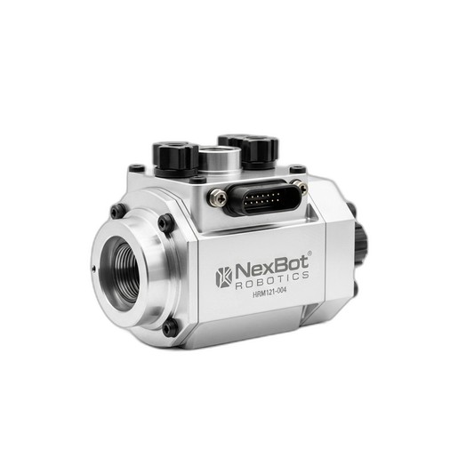
- NexBot Robotics HRM121-004 Harmonic Gearbox: A high-precision drive with a 121:1 ratio and near-zero backlash, critical for accuracy.
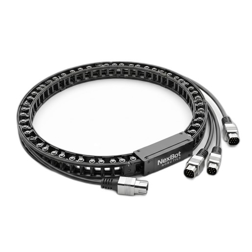
- NexBot Vision 541-003 Cable Carrier: To protect and guide essential data and power lines.
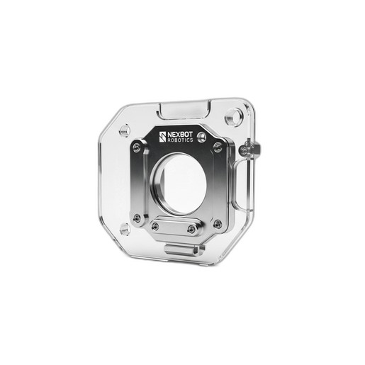
- NexBot Vision 823-003 Splash Guard: A durable polycarbonate shield for environmental protection.
Inspect all new parts for any signs of shipping damage before proceeding.
Step 2: Installing the HRM121-004 Harmonic Gearbox
The harmonic gearbox is the heart of the joint, translating motor rotation into precise, powerful movement. Proper installation is crucial for achieving its specified performance.
- Surface Preparation: Clean the mounting surfaces on both the robot link and the motor flange. Ensure they are free of oil, debris, and burrs. Any imperfection can cause misalignment, leading to premature wear.
- Alignment: Carefully align the gearbox with the mounting holes on the robot arm structure. Use alignment pins if specified by the robot manufacturer. The fit should be snug but not forced.
- Fastener Insertion: Loosely insert all mounting bolts by hand to ensure proper thread engagement. Never use power tools for initial threading to avoid cross-threading.
- Torque Sequence: This is a critical step. Tighten the mounting bolts in a star or crisscross pattern to ensure the gearbox is seated evenly. Use a calibrated torque wrench and follow the manufacturer's specified torque values. The HRM121-004 is designed to handle significant operational torque (up to 180 Nm), but its mounting integrity depends on correct installation.
- Motor Integration: Mount the motor to the gearbox input, again ensuring clean surfaces and proper alignment. Follow a similar star-pattern torque sequence for the motor bolts. The near-zero backlash of the HRM121-004 is only effective if the entire drive train is rigidly coupled.
Step 3: Managing Cables with the Vision 541-003 Cable Carrier
With the mechanical heart of the joint installed, the next step is to manage the nervous system: the cables. Unmanaged cables are a primary failure point, susceptible to abrasion, pinching, and stress.
- Plan the Route: Lay out the path for the cable carrier along the robot arm. Ensure its movement path is unobstructed and allows for the full range of motion of the joint without binding or over-stretching.
- Open the Carrier: The NexBot Vision 541-003 features an easy-open design. Open the crossbars along the length of the carrier where you will be laying the cables.
- Lay the Cables: Place your cables inside the carrier. For high-performance industrial protocols like PROFINET, it's vital to avoid sharp bends or compression. Do not overfill the carrier; a good rule of thumb is to leave at least 10% free space. This prevents cable-on-cable abrasion and allows for heat dissipation.
- Secure and Close: Once all cables are properly laid out, close the carrier crossbars, ensuring they snap securely into place. Mount the ends of the carrier to the designated points on the robot arm, providing strain relief for the cables at both ends.
Step 4: Shielding the Assembly with the Vision 823-003 Splash Guard
Industrial environments are often harsh, with coolants, lubricants, and cleaning agents present. The final step is to protect your newly assembled joint from these contaminants.
- Clean the Sealing Surface: Wipe down the area where the splash guard will be mounted to ensure it is free of any fluids or debris. This will ensure a proper seal.
- Position the Guard: Place the NexBot Vision 823-003 Splash Guard over the joint assembly. Its transparent polycarbonate construction allows for visual inspection of the joint without requiring removal, a key benefit for quick maintenance checks.
- Secure the Guard: Fasten the splash guard using the provided mounting points. Ensure an even, snug fit, but avoid over-tightening the fasteners, which could damage the polycarbonate material. The goal is to create a reliable barrier against fluid ingress, protecting the sensitive gearbox and electrical connections within.
Step 5: Final Checks and Commissioning
With the assembly complete, it's time to bring the robot back online.
- Remove LOTO: Following your facility's safety protocols, remove the lockout/tagout devices.
- Power On: Power up the robot system. Listen for any unusual noises from the new joint.
- Homing and Calibration: Perform the robot's standard homing procedure. You may need to run a calibration routine to teach the controller the new joint's precise position, especially after replacing a key drive component.
- Test Run: Execute a test program at low speed, moving the new joint through its entire range of motion. Visually inspect the joint, cable carrier, and splash guard to ensure everything is moving freely and correctly. Once confirmed, gradually increase the speed to normal operational levels.
By following these steps, you have successfully serviced and protected a critical robotic joint, restoring its precision and ensuring its long-term reliability with quality NexBot Robotics components.