Introduction: Giving Robots the Sense of Touch
Industrial robots are renowned for their speed, strength, and repeatability. However, for applications requiring finesse—such as intricate assembly, polishing, or deburring—pure position control is not enough. These tasks demand a sense of touch. This is where 6-axis force/torque (F/T) sensors come in, providing the rich, multi-dimensional feedback needed for adaptive and precise robotic operations. By measuring forces and torques along all three Cartesian axes (Fx, Fy, Fz, Tx, Ty, Tz), these sensors allow a robot to feel its interaction with the workpiece and adjust its path in real-time.
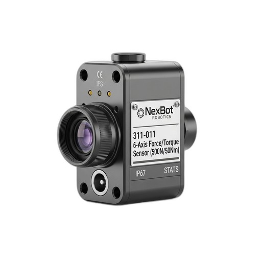
This guide provides a practical, step-by-step walkthrough for installing and calibrating a 6-axis F/T sensor, using the NexBot Vision 311-011 as our reference model. Following these procedures ensures you get reliable data, protect your equipment, and unlock the full potential of force-sensitive applications.
Step 1: Pre-Installation Checklist and Safety
Proper preparation is the key to a smooth installation. Before you begin, ensure you have gathered all necessary components and have taken appropriate safety measures.
Safety First:
- Power Down: Completely power down the robot and its controller. Follow standard lockout/tagout (LOTO) procedures to prevent accidental startup.
- Review Documentation: Have the manuals for your robot, the F/T sensor, and any end-of-arm tooling (EOAT) on hand. Pay close attention to mechanical load limits and electrical specifications.
Component Checklist:
- The Sensor: Your 6-axis F/T sensor, such as the NexBot Vision 311-011.
- Mounting Hardware: High-grade bolts of the correct length and thread to attach the sensor to the robot flange and the EOAT to the sensor. Ensure they meet the torque requirements specified by the manufacturer.
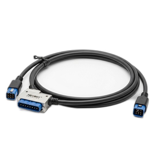
- Cabling: A high-quality communication and power cable compatible with your sensor. The Vision 311-011, for example, requires a 24VDC power supply and communicates via EtherCAT, so an appropriate M12 or similar industrial connector cable is needed.
- Tools: A calibrated torque wrench, Allen keys, and any other tools required for your specific robot and EOAT.
- Software: Access to the robot controller's programming environment and any necessary drivers or configuration files (e.g., the EtherCAT ESI file for the sensor).
Step 2: Mechanical Installation
The F/T sensor is typically mounted between the robot's wrist flange (often ISO 9409-1) and the EOAT. This positioning ensures it measures all forces and torques being applied by the tool.
- Inspect Flanges: Ensure the mounting surfaces on the robot wrist and your tool are clean, flat, and free of burrs or debris. Any imperfection can introduce measurement errors.
- Attach Sensor to Robot: Carefully align the sensor with the mounting pattern on the robot flange. Insert and hand-tighten the bolts. Then, using a torque wrench, tighten the bolts in a star pattern to the specified torque value. This ensures even clamping pressure.
- Attach EOAT to Sensor: In the same manner, mount your gripper, sander, or other EOAT to the tool-side face of the sensor. Again, align the mounting holes, hand-tighten the bolts, and then torque them to the manufacturer's specification in a star pattern. The rugged, IP67-rated construction of sensors like the Vision 311-011 is a significant advantage here, protecting the sensitive internal electronics from dust and fluids common in industrial environments.
Step 3: Electrical Connection and Communication
With the sensor mechanically secure, the next step is to establish power and communication.
- Connect the Cable: Securely connect the sensor cable to the sensor's port. Ensure the connector is fully seated and locked to maintain its IP rating. Route the cable along the robot arm, using the robot's built-in cable management system to prevent pinching, stretching, or snagging during operation.
- Provide Power: Connect the power lines of the cable to a stable 24VDC power supply as specified in the sensor's manual.
- Establish Communication: For an EtherCAT sensor like the Vision 311-011, this involves connecting the communication lines to your EtherCAT network. This is typically done by daisy-chaining it with other EtherCAT devices or connecting it directly to an EtherCAT master port on the robot controller or a PLC.
- Configure the Network: Power on the robot controller. In your engineering software, you will need to scan the EtherCAT bus or manually add the sensor using its ESI (EtherCAT Slave Information) file. Once the sensor is recognized by the network master, you can configure its data transmission parameters.
Step 4: Sensor Calibration and Tool Definition
Calibration is critical for accurate measurements. It involves teaching the system to ignore the static weight and center of gravity of the EOAT, so that it only reports external forces applied during an operation.
- Zeroing (Taring) the Sensor: The most basic calibration is a zeroing procedure. In the robot's software interface, find the function to tare or zero the F/T sensor. With the EOAT attached and the robot holding still in a neutral orientation (e.g., tool pointing straight down), execute the zeroing command. This establishes the current gravitational load of the tool as the baseline 'zero' reading.
- Defining the Tool Center Point (TCP): Accurately define the TCP of your EOAT in the robot controller. An incorrect TCP will cause the sensor to report false torque values when the robot rotates its wrist.
- Payload and Center of Gravity: Define the payload mass and center of gravity of your EOAT in the robot's software. Many modern robot controllers have semi-automated routines to calculate this. An accurate payload definition helps the robot's motion planner and also allows the system to compensate for gravitational forces as the tool's orientation changes, leading to cleaner force readings.
Step 5: Integration and Verification
With the sensor installed and calibrated, you can begin integrating its data into your robot program.
- Read Sensor Data: Start by writing a simple routine to continuously read and display the six force and torque values from the sensor. Move the robot's joints manually and gently press on the EOAT from different directions. You should see the corresponding Fx, Fy, and Fz values change in a logical way.
- Implement a Simple Force-Controlled Move: The true power of the sensor is unlocked with force-controlled motion. Program a simple task, such as moving the robot down towards a surface until a specific force is detected.
Example Logic: MOVE_LINEAR(Target_Position) UNTIL (GET_FORCE(Z) > -20.0 N)
This command tells the robot to move towards a point but to stop as soon as it measures a downward force of 20 Newtons, indicating contact.
Conclusion: Mastering Advanced Robotics
Properly installing and calibrating a 6-axis force/torque sensor transforms a standard industrial robot into a highly adaptive and sensitive machine. This capability is essential for automating tasks that were once too complex or delicate for robots. While this guide covers the fundamental steps, mastering advanced force control strategies, diagnostic procedures, and maintenance workflows requires deeper knowledge.
For teams looking to build comprehensive expertise in robotic systems maintenance, including the integration of sophisticated components like sensors and safe servo motor replacement, a structured training program is invaluable. The NexBot Robotics Training Course 912-010 (NXB-KIT-912-010) offers instructor-led, hands-on learning to equip your technicians with the skills they need to maximize uptime and performance in a modern automated facility.