Introduction: The Power of Touch in Robotics
Modern industrial robots are capable of incredible precision and speed, but to truly elevate their functionality for complex tasks like assembly, polishing, or intricate material handling, they need a sense of touch. This is where a 6-axis force/torque (F/T) sensor becomes indispensable. By providing real-time feedback on all forces and torques being applied at the end-effector, these sensors allow robots to adapt to variations, handle delicate parts, and perform tasks that require human-like dexterity.
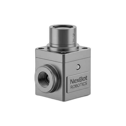
The NexBot Drives 311-006 6-Axis Force/Torque Sensor is engineered to provide this critical data with high precision. This guide will walk you through the essential steps to correctly install, configure, and calibrate your F/T sensor, ensuring you get the most accurate and reliable data for your application.
Pre-Installation Checklist
Before you begin the installation process, a little preparation goes a long way. Gather the following tools and components to ensure a smooth and efficient setup:
- Your Robot and Controller: Ensure the robot is powered down and in a safe, stable position.
- NexBot Drives 311-006 Sensor: Unbox the sensor and inspect it for any signs of shipping damage.
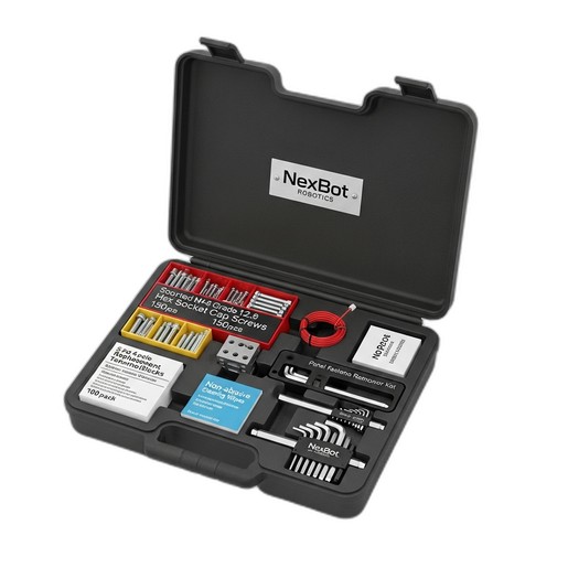
- Mounting Hardware: You will need appropriate screws to mount the sensor to the robot arm flange and to attach your end-of-arm tooling (EOAT) to the sensor. The NexBot Vision 763-003 Multi-Part Maintenance Kit (NXB-KIT-763-003) contains a comprehensive set of Grade 12.9 hex socket cap screws (M4-M8) and precision hex keys, making it an ideal companion for this task.
- Cabling: The appropriate EtherCAT and power cables for your sensor and controller.
- Robot Controller Software: Access to the robot's programming environment to configure the new hardware.
- Technical Documentation: Keep the sensor's and robot's manuals handy for specific torque values and pinout diagrams.
Step 1: Mechanical Installation
The first step is to physically mount the sensor onto the robot arm. Accuracy here is key, as any misalignment can introduce measurement errors.
- Power Down: Ensure the robot is completely powered off and locked out according to your facility's safety procedures.
- Clean Mounting Surfaces: Use the non-abrasive cleaning wipes from the NXB-KIT-763-003 to clean both the robot arm flange and the sensor's mounting surface. This removes any debris or oils that could prevent a flush fit.
- Align the Sensor: Carefully align the sensor's mounting holes with the holes on the robot arm flange. Pay close attention to the orientation of the sensor's coordinate system, which is typically marked on the housing. This orientation is crucial for interpreting the force and torque data correctly in your software.
- Secure the Sensor: Using the correct size and length screws, fasten the sensor to the robot arm. Tighten the screws in a star pattern to ensure even pressure. Refer to the sensor's documentation for recommended torque specifications to avoid over-tightening.
- Attach End-of-Arm Tooling (EOAT): Once the sensor is secure, attach your gripper or other EOAT to the tool-side mounting face of the sensor, again following proper fastening procedures.
Step 2: Electrical Integration
With the sensor mechanically mounted, it's time to connect it electrically. The NexBot Drives 311-006 uses a 24VDC power supply and communicates via EtherCAT, a high-performance industrial Ethernet protocol.
- Connect Power: Connect the 24VDC power cable to the sensor's power port. Ensure the power supply is stable and meets the sensor's requirements. Do not apply power yet.
- Connect Communication Cable: Connect the EtherCAT cable from the sensor to your robot controller's EtherCAT network port. EtherCAT's real-time capabilities are essential for applications requiring low-latency feedback, such as force control or collision detection.
- Cable Management: Securely route the cables along the robot arm, using the robot's built-in cable management system if available. Ensure there is enough slack to allow for the robot's full range of motion without straining the cables or connectors.
Step 3: Software Configuration
Now, you need to tell the robot controller that a new device is present on the network.
- Power On: Power on the robot controller and then the sensor's power supply.
- Install Device Description File: Most EtherCAT devices require an ESI (EtherCAT Slave Information) file. You will need to import the ESI file for the NXB-SNS-311-006 into your controller's engineering software. This file tells the master how to communicate with the sensor.
- Network Scan: Perform a network scan or bus scan from your controller's software. The controller should detect the new F/T sensor on the EtherCAT bus.
- Map I/O Data: Once detected, you will need to map the sensor's process data (the Fx, Fy, Fz, Tx, Ty, Tz values) to variables within your robot program. This allows your program to read the force and torque values in real-time.
Step 4: Calibration and Tool Definition
Calibration is the most critical software step for ensuring data accuracy. This process involves defining the tool's properties and zeroing the sensor.
- Tool Center Point (TCP) and Payload Definition: In your robot's software, you must accurately define the TCP, weight, and center of gravity of the EOAT that is attached to the sensor. The F/T sensor measures all forces acting upon it, including the weight of the tool itself. The robot controller uses the payload data to compensate for gravity, so the program only sees the external forces applied by the task.
- Zeroing the Sensor: Before use, the sensor must be zeroed. This establishes a baseline reading of zero when no external forces are applied. To do this, orient the robot so the sensor is in a position with no external load (other than the defined tool). Use the provided software function to send a zeroing command to the sensor. It's good practice to re-zero the sensor periodically, especially after a significant temperature change or if the robot has been powered off for an extended period.
Step 5: Testing and Validation
Finally, verify that everything is working as expected.
- Live Data Monitoring: Create a simple program or use a monitoring tool to display the six axes of force and torque data in real-time.
- Manual Test: With the robot stationary, gently push on the EOAT in various directions (e.g., along the X, Y, and Z axes). You should see the corresponding force values change on your monitor. Apply a slight twisting motion to see the torque values respond.
- Programmatic Test: Write a simple test routine that moves the robot and uses the sensor data, for example, stopping a motion when a certain force threshold is detected. This confirms that the entire system—mechanical, electrical, and software—is integrated correctly.
Enhancing Safety
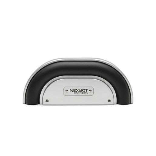
While an F/T sensor can be used for collision detection, it's often part of a larger safety ecosystem. For robust protection of equipment and personnel, consider dedicated safety devices like the NexBot Drives 632-006 Collision Sensor Bumper (NXB-SNS-632-006), which provides a direct and reliable signal upon physical contact, complementing the nuanced data from your F/T sensor.
By following these steps, you will have successfully installed and configured your NexBot Drives 311-006 sensor, unlocking a new level of intelligence and capability for your robotic applications.