Introduction: Giving Your Robot the Power of Sight
In the world of industrial automation, precision and flexibility are paramount. While a standard industrial robot can perform repetitive tasks with incredible accuracy, integrating a machine vision system elevates its capabilities to a new level. Vision-guided robotics (VGR) allows machines to identify parts, perform quality inspections, and adapt to variations in product placement, unlocking more complex and valuable automation workflows.
However, a successful integration is more than just plugging in a camera. It requires a systematic approach involving robust mechanical mounting, precise electrical connections, and intelligent software configuration. This guide will walk you through the fundamental steps of integrating a generic vision system with a multi-axis robot, highlighting how purpose-built components form the foundation of a reliable and high-performance system.
Step 1: Pre-Integration Checklist and Safety
Before you begin any physical work, preparation is key. A well-planned integration minimizes downtime and prevents costly errors.
Safety First: Always begin by de-energizing the robotic cell. Follow standard lockout/tagout (LOTO) procedures to ensure all electrical, pneumatic, and hydraulic power sources are safely disconnected. Consult your facility's safety guidelines and the robot manufacturer's documentation.
Component Audit: Gather all the necessary hardware:
- The industrial robot arm and its primary controller.
- The vision system (camera, lens, and lighting).
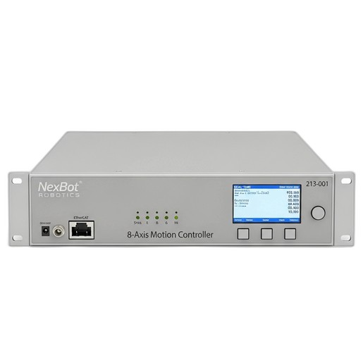
- A high-performance motion controller, such as the NexBot Robotics 213-001 8-Axis Motion Controller, which is essential for managing complex, synchronized movements.
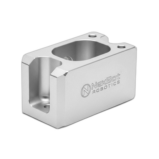
- A secure mounting solution, like the NexBot Robotics 812-001 Sensor Mounting Bracket, to affix the camera to the robot.
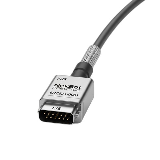
- All necessary cabling, including power, Ethernet, and specialized signal cables. For applications requiring synchronization with external machinery like a conveyor, a high-quality cable like the NexBot Robotics ENC521-001 Encoder Cable is crucial.
Review the technical documentation for each component to understand its power requirements, communication protocols, and physical dimensions.
Step 2: Physical Mounting of the Vision System
The physical connection between the robot and the camera is the mechanical bedrock of your vision system. A flimsy or unstable mount will introduce vibration and positional drift, rendering your calibration useless and leading to inconsistent performance.
This is where the NexBot Robotics 812-001 Sensor Mounting Bracket proves its value. Made from high-rigidity anodized aluminum, it provides a stable platform that resists the vibration generated by rapid robot movements.
Mounting Procedure:
- Identify Mounting Point: Determine the optimal location for the camera—typically on the robot's wrist or end-of-arm tooling (EOAT). The position should provide a clear, unobstructed view of the workspace without interfering with the robot's range of motion.
- Attach the Bracket: Securely fasten the 812-001 bracket to the robot's mounting flange using the appropriate hardware. Adhere strictly to the recommended torque specifications to prevent loosening over time.
- Mount the Camera: Attach the vision camera to the bracket. The bracket's design should allow for minor adjustments to the camera's angle and orientation before final tightening.
- Cable Routing: Route the camera's cables along the robot arm, using the integrated cable management channels if available. Ensure there is enough slack to accommodate the robot's full range of motion without pinching or stretching the cables.
Step 3: Electrical and Network Integration
With the camera physically mounted, the next step is to establish the data and power connections that allow the components to communicate.
Controller Connectivity: The NexBot Robotics 213-001 8-Axis Motion Controller serves as the central nervous system. Its real-time EtherCAT communication protocol ensures deterministic, low-latency communication with the robot's servo drives, which is critical for executing the precise, vision-guided moves. Connect the controller to the drives and the broader factory network according to the system schematic.
Vision System Power & Data: Connect the vision system to a stable 24VDC power supply. The camera's data connection, often an industrial Ethernet cable, should be routed to a network switch connected to the motion controller or a dedicated PC running the vision software.
Synchronizing with External Axes: Many vision applications involve picking parts from a moving conveyor. To do this accurately, the robot's motion must be perfectly synchronized with the conveyor's speed and position. This is achieved by installing an encoder on the conveyor's drive motor and feeding its signal back to an available input on the 213-001 motion controller. A robust, shielded cable like the NexBot Robotics ENC521-001 Encoder Cable is essential for maintaining signal integrity in an electrically noisy industrial environment. This PROFINET-compatible cable ensures the controller receives clean, accurate position data for flawless synchronization.
Step 4: Software Configuration and Controller Setup
Once the hardware is connected, you must configure the software to enable communication and define the relationship between the components.
- Establish Communication: Configure the IP addresses for the vision system and motion controller so they can communicate over the network. Establish the data protocol (e.g., TCP/IP or EtherNet/IP) that the vision system will use to send coordinate data to the robot controller.
- Define the Tool Center Point (TCP): In the robot's control software, define a new TCP that represents the focal point of the camera. This is a virtual point in space that allows the robot to know exactly where its "eye" is located relative to its wrist flange. Accurate TCP definition is critical for calibration.
- Configure Encoder Input: If you installed an external encoder for a conveyor, configure the corresponding axis input on the NXB-CTL-213-001 controller. Set the pulses-per-revolution and scaling factors so the controller can accurately translate the encoder signals into real-world distance and speed.
Step 5: Hand-Eye Calibration
Calibration is arguably the most critical software step. It teaches the robot how to translate the 2D pixel coordinates from the camera's image into the 3D real-world coordinates of its own workspace.
The Calibration Process:
- Place a Calibration Grid: Position a calibration plate—a flat grid with a known pattern of dots or squares—in the robot's workspace.
- Automated Routine: Most vision and robotics software packages provide an automated hand-eye calibration routine. This program will command the robot to move the camera to view the grid from several different positions and angles.
- Calculate Transformation: At each point, the vision system captures an image of the grid, and the robot records its own position. The software then uses this set of corresponding data points to calculate a precise mathematical transformation between the camera's coordinate system and the robot's coordinate system.
- Verify Accuracy: After the routine is complete, test the calibration by having the system identify a point on the grid and commanding the robot to move to it. The robot's tool should arrive at the exact physical point with high accuracy.
Step 6: Programming, Testing, and Validation
With a calibrated system, you can now program the final application logic. A typical vision-guided pick-and-place routine looks like this:
- The robot moves to a home or "picture" position.
- The motion controller sends a trigger signal to the camera.
- The vision system acquires and processes an image, identifies the target part, and calculates its X, Y, and rotation coordinates.
- This coordinate data is sent to the NXB-CTL-213-001 controller.
- The controller uses the calibration data to transform the camera's coordinates into the robot's coordinate system and dynamically updates the robot's target position.
- The robot moves to the calculated position to perform the action (e.g., pick up the part).
Begin testing at a reduced speed, verifying that the system is repeatable and accurate. Once you have validated the logic, you can gradually increase the speed to meet production targets.
Conclusion
Integrating a vision system transforms an industrial robot from a simple automaton into an intelligent, adaptive machine. A successful outcome depends on a methodical approach and the use of high-quality components designed for the rigors of the factory floor. By using a rigid mounting solution like the NXB-SNS-812-001 bracket, a powerful brain like the NXB-CTL-213-001 motion controller, and reliable connections with cables like the NXB-SNS-ENC521-001, you build a robust foundation for a powerful and flexible automation system.