Introduction: The Critical Role of Emergency Stop Systems
In any industrial robotics application, safety is not an option—it's a fundamental requirement. At the heart of any robust safety system is the emergency stop (E-Stop) circuit. This system provides a foolproof method for personnel to halt machine motion immediately in the event of a hazard. Properly integrating an E-Stop device with a dedicated safety controller ensures that this critical function operates reliably and predictably, protecting both operators and expensive equipment.
This guide will walk you through the essential steps of physically wiring and logically configuring an emergency stop push-button with a modern safety controller. We will cover the core principles, component selection, and the validation process required to build a safety circuit that you can trust. Following these steps helps ensure your robotic cell meets necessary safety performance levels and provides a safer working environment.
Required Components and Tools
Before beginning the integration, gather the necessary components and tools. Using high-quality, certified components is crucial for the integrity of your safety system.
Key Components:
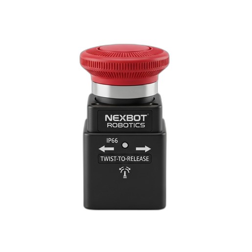
- Emergency Stop Device: A dual-channel, normally closed (NC) push-button. The NexBot Robotics 622-007 Emergency Stop Device is an excellent choice, featuring a 40mm mushroom head for easy activation, a rugged IP66 rating for industrial environments, and a simple twist-to-release reset mechanism.
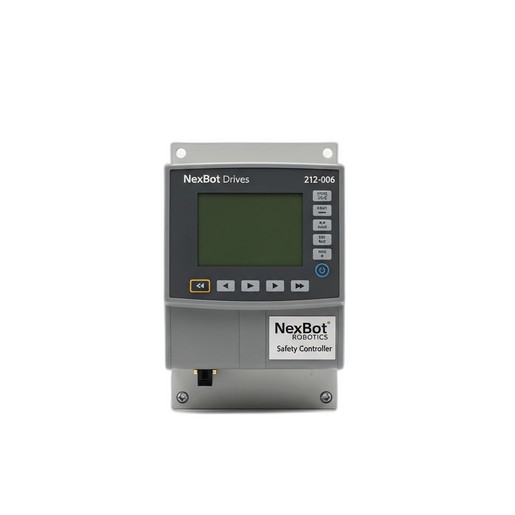
- Safety Controller/PLC: A programmable controller designed specifically for safety-rated applications. The NexBot Drives 212-006 Safety Controller is designed for this purpose, offering dedicated safety I/O and communication over protocols like PROFIsafe.
- Power Supply: A stable 24VDC power supply to power the safety controller and E-Stop circuit.
- Contactors/Relays: Safety-rated contactors or relays that will be controlled by the safety controller to cut power to the robot's motors or drives.
- Appropriate Wiring: Shielded, multi-conductor cable suitable for 24VDC control signals.
Essential Tools:
- Wire strippers and cutters
- Terminal screwdrivers (various sizes)
- Multimeter for continuity and voltage checks
- Laptop with safety controller configuration software
Step 1: Understanding the Safety Circuit Logic
Modern safety circuits rely on the principle of dual-channel redundancy and continuous monitoring. An E-Stop button like the NXB-GEN-622-007 is equipped with two separate, electrically isolated normally closed (NC) contacts. In its normal, un-pressed state, both contacts are closed, allowing current to flow through two independent channels to the safety controller.
When the E-Stop is pressed, both NC contacts open simultaneously, interrupting the signal on both channels. The safety controller, such as the NXB-CTL-212-006, is programmed to monitor these two inputs. It looks for two key conditions:
- Concordance: Both channels must change state together (within a very short time discrepancy). If one channel opens but the other remains closed, the controller registers a fault, as this could indicate a welded contact or a wiring short.
- State: When both channels are open, the controller enters a safe state, de-energizing its safety outputs.
This dual-channel architecture ensures that a single point of failure (like a stuck contact or a single broken wire) does not lead to a failure of the entire safety function.
Step 2: Physical Installation and Mounting
The E-Stop device must be installed in a location that is easily visible and accessible to operators from any position where they might need to interact with the robot. Mount the NexBot Robotics 622-007 securely to a control panel or machine frame. Its IP66 rating ensures protection against dust and powerful water jets, making it suitable for a wide range of factory conditions. Ensure the panel cutout is the correct size and that the device is tightened sufficiently to maintain its environmental seal.
Mount the safety controller and any associated relays inside a secure electrical enclosure, ensuring adequate ventilation and separation from high-voltage components to prevent electrical noise interference.
Step 3: Wiring the E-Stop to the Safety Controller
Proper wiring is critical. Always refer to the specific wiring diagrams provided with your components. However, the general procedure for a dual-channel E-Stop is as follows:
- Power the Controller: Connect your 24VDC power supply to the designated power input terminals on the NexBot Drives 212-006 Safety Controller.
- Connect Channel 1: Run a wire from the 24V+ terminal of your power supply to one side of the first NC contact on the E-Stop button. Run a second wire from the other side of that same NC contact to the first dedicated safety input on the controller (e.g., SI 0).
- Connect Channel 2: In the same manner, run a wire from the 24V+ terminal to one side of the second NC contact on the E-Stop. Run another wire from the other side of this contact to the second dedicated safety input on the controller (e.g., SI 1).
- Connect Safety Outputs: Wire the safety outputs of the controller to the coils of your main power contactors. When the controller enters a safe state, it will de-energize these outputs, causing the contactors to open and cut power to the robot's drive system.
Use a multimeter to check for continuity on each channel before applying power to verify your connections.
Step 4: Configuring the Safety Controller Software
With the physical wiring complete, the next step is to configure the logic within the safety controller.
- Establish Communication: Connect your laptop to the controller, typically via an Ethernet or USB port, and launch the manufacturer's safety programming software.
- Configure Inputs: In the software, define the two physical inputs you used (e.g., SI 0 and SI 1) as a paired E-Stop function.
- Add E-Stop Function Block: Drag and drop the E-Stop function block from the software library into your logic program. Assign your configured inputs to this block.
- Link to Outputs: Connect the output of the E-Stop function block to the safety outputs that control your power contactors. This logic dictates that if the E-Stop block is not satisfied (i.e., the button is pressed), the outputs will be de-energized.
- Set Up Communication: If your system requires it, configure the safety network communication. The NXB-CTL-212-006 uses PROFIsafe over PROFINET, allowing it to communicate the safety status securely to a standard PLC or HMI for system monitoring and diagnostics.
- Download and Secure: Download the configuration to the controller. Most safety PLCs require a password or physical key switch to prevent unauthorized changes.
Step 5: Testing and Validation
A safety system is not complete until it has been thoroughly tested and validated. This is a mandatory step to ensure it performs as expected.
- Power-On Test: With the E-Stop in its normal (released) state, power on the system. The safety controller should indicate a healthy, closed-circuit status, often with green LEDs.
- Functional Test: Press the E-Stop button. Verify that the safety controller's outputs immediately de-energize and that power to the robot's motors is cut. The robot arm should stop immediately and lose all drive power.
- Reset Test: With the E-Stop still pressed, attempt to reset the system using the standard reset button. The system should not be able to restart.
- Release and Reset: Twist to release the E-Stop button. The E-Stop circuit should now be healthy, but the system should remain in a safe state until a separate, deliberate reset signal is given. Once the reset button is pressed, the safety outputs should re-energize, allowing the robot to be powered on again.
- Fault Injection (Advanced): For higher performance level validation, you may need to simulate faults, such as disconnecting one of the E-Stop channels, to ensure the controller correctly detects the discrepancy and enters a safe state.
Document all test results as part of your machine's technical file.
Conclusion: Building a Foundation of Safety
Integrating an emergency stop circuit is a foundational skill for any robotics engineer or technician. By using certified components like the NexBot Robotics 622-007 E-Stop and the NexBot Drives 212-006 Safety Controller, and by following a methodical process of wiring, configuration, and validation, you can build a reliable safety system that protects personnel and complies with critical industry standards like ISO 13849. Always prioritize safety, double-check your work, and consult the relevant standards and manufacturer documentation.