Introduction: The Foundation of a High-Performance Robotic System
Building a reliable and safe automated system requires more than just a robot arm; it demands the precise integration of core components that govern motion and ensure operational safety. The servo motor, the safety controller, and the cables that connect them are the unsung heroes of industrial automation. A properly integrated system results in accurate, repeatable movements and a secure environment for personnel. A poorly integrated one can lead to performance issues, unexpected downtime, and significant safety risks.
This guide provides a step-by-step walkthrough for integrating a high-performance AC servo motor with a certified safety controller. We will use three key components from the NexBot Robotics catalog as our reference: the NexServo EcoLine AC25 (NXB-SRV-ACE-025-A) for powerful and precise motion, the NexBot Robotics 212-001 Safety Controller (NXB-CTL-212-001) for robust, SIL3/PLe certified safety, and the NexBot Encoder Cable for R-20 J3 (NXB-CBL-ENC-R20-J3) to ensure flawless communication between them. Following these steps will help you build a robust foundation for your next automation project.
Step 1: Pre-Installation Checklist and Component Overview
Before you begin, preparation is key. A successful integration starts with understanding your components and having the right tools on hand.
Component Breakdown:
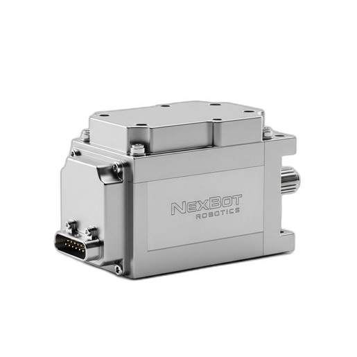
- NexServo EcoLine AC25 (NXB-SRV-ACE-025-A): This is the muscle of your system. As a 48VDC AC servo motor, it provides the rotational force (up to 25 Nm of torque) needed for motion. Its integrated encoder provides high-resolution position feedback, and it communicates over the PROFINET industrial Ethernet protocol for seamless integration with your primary robot controller.
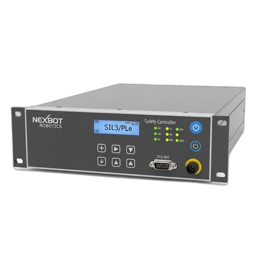
- NexBot Robotics 212-001 Safety Controller (NXB-CTL-212-001): This is the brain of your safety system. Operating at 24VDC, it is certified to the highest standards (SIL3/PLe). It uses Fail Safe over EtherCAT (FSoE) to monitor safety devices like E-stops and light curtains, and can safely disable motion by controlling the servo drive's Safe Torque Off (STO) function.
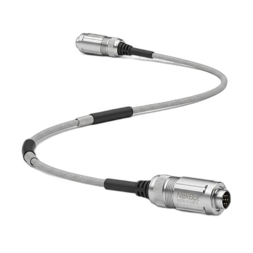
- NexBot Encoder Cable (NXB-CBL-ENC-R20-J3): This is the nervous system connecting the motor's encoder to the drive. This high-quality cable is crucial for transmitting clean, accurate position data, which is essential for both precise motion control and safety functions like Safe Position monitoring.
Required Tools & Precautions:
- Appropriate torque wrenches for mechanical mounting.
- Wire strippers, crimpers, and screwdrivers for electrical connections.
- Laptop with configuration software for your PLC/robot controller and safety controller.
- Ethernet cables for PROFINET and EtherCAT/FSoE networks.
- Personal Protective Equipment (PPE), including safety glasses and gloves.
- Ensure all power sources are de-energized and locked-out/tagged-out (LOTO) before starting any physical installation.
Step 2: Mechanical Installation and Mounting
Proper mechanical installation prevents vibration, misalignment, and premature wear.
- Mounting the Servo Motor: Securely mount the NexServo EcoLine AC25 to its designated location on the robot axis or machine frame. Use the correct size and grade of bolts and tighten them to the manufacturer's specified torque values. Ensure the motor shaft is perfectly aligned with the load's coupling to prevent binding and excessive stress on the motor bearings.
- Mounting the Safety Controller: Install the NexBot 212-001 Safety Controller inside your main control cabinet. Typically, this is done on a standard DIN rail. Ensure there is adequate space around the controller for ventilation and cable routing. Keep high-voltage power cables separate from low-voltage signal and network cables to minimize electromagnetic interference (EMI).
Step 3: Electrical Wiring and Connections
Accurate wiring is critical for both functionality and safety. Always refer to the specific pinout diagrams for each component.
- Connect the Encoder Cable: Connect one end of the NexBot Encoder Cable (NXB-CBL-ENC-R20-J3) to the corresponding encoder port on the NexServo motor. Route the cable carefully, avoiding sharp bends or proximity to high-power motor cables. Connect the other end to the servo drive's encoder input port. The secure connection ensures that the drive receives uninterrupted, high-fidelity position feedback.
- Wire the Servo Motor Power: Connect the 48VDC power leads from the servo drive to the motor's power connector. Ensure the polarity is correct and that the wire gauge is sufficient for the motor's peak current draw.
- Wire the Safety Controller: Connect a stable 24VDC power supply to the NexBot 212-001 controller. Next, wire your safety input devices (e.g., emergency stop buttons, light curtains, door switches) to the controller's safety input terminals. Finally, connect the safety output from the controller to the Safe Torque Off (STO) terminals on the servo drive that powers the NexServo motor. When the safety circuit is tripped, this connection will allow the 212-001 to safely remove torque from the motor.
Step 4: Network Integration and Configuration
With the hardware in place, the next step is to configure the network communication that allows the components to work together.
- PROFINET Setup (Servo Motor): Connect the NexServo EcoLine AC25 (via its drive) to your PROFINET network. Using your engineering software, assign a unique device name and IP address to the servo drive. Integrate it into your main PLC or robot controller project. You will then be able to send motion commands (position, velocity, torque) to the motor over the network.
- FSoE Setup (Safety Controller): Connect the NexBot 212-001 to your EtherCAT network. In your EtherCAT master configuration, enable FSoE communication. Using the safety configuration software, create your safety logic. For example, you can program a logic block where 'IF E-Stop is pressed OR Light Curtain is broken, THEN activate safety output'. This output is physically wired to the STO input on the servo drive, creating a complete, certified safety function.
Step 5: System Commissioning and Testing
Commissioning is the final validation step to ensure everything works as intended.
- Power-On Sequence: Apply power first to the 24VDC control circuits, including the safety controller. Verify that the controllers boot up without faults. Once control power is stable, apply the 48VDC drive power for the servo motor.
- Motor Tuning: Perform an initial 'jog' of the motor at a very low speed to confirm the direction of rotation is correct and the encoder feedback is stable. Use the servo drive's software to perform an auto-tune or manually tune the control loops (proportional, integral, derivative gains) to optimize the motor's responsiveness and stability for your specific application.
- Safety Function Validation: This is the most critical part of commissioning. Systematically test every safety function. Press each E-stop button, interrupt each light curtain, and open each safety gate. In every case, verify that the NexBot 212-001 controller detects the event and safely disables the NexServo motor via the STO function. Document the results of each test as part of your machine's safety validation report.
Step 6: Troubleshooting Common Integration Issues
Even with careful planning, you may encounter issues. Here are a few common problems and their solutions:
- Issue: Motor vibrates or is unstable.
- Possible Cause: Poor tuning, mechanical resonance, or noisy encoder signal.
- Solution: Re-run the auto-tuning process. Check the integrity of the NexBot Encoder Cable connection at both ends. Ensure the cable is shielded and grounded correctly.
- Issue: Safety Controller shows a fault.
- Possible Cause: Wiring error on an input/output, FSoE address mismatch, or a logic error.
- Solution: Double-check all wiring against the diagrams. Verify the FSoE address is unique and correctly set in the master. Review the safety logic to ensure it is complete and error-free.
- Issue: No communication with the servo drive.
- Possible Cause: Incorrect IP address, device name conflict, or a faulty network cable.
- Solution: Use a network scanning tool to verify the drive is visible on the PROFINET network. Confirm the device name and IP address in your project match what is set on the drive.
By methodically following these integration steps, you can successfully combine motion and safety components to create a robotic cell that is not only highly productive but also fundamentally safe.