In the world of industrial robotics, unplanned downtime is the ultimate enemy. While major components like motors and gearboxes often get the most attention, the reliability of an entire robotic cell frequently hinges on the health of its smaller, yet equally critical, components. A robust preventive maintenance (PM) schedule that includes sensors, connectors, and controllers is the key to maximizing operational efficiency and avoiding costly emergency repairs.
This guide will focus on proactive maintenance strategies for three foundational component types: absolute encoders for positioning, fieldbus connectors for communication, and safety controllers for operational integrity. By understanding the common wear indicators and implementing regular checks, you can significantly enhance the longevity and performance of your robotic systems.
Maintaining Positioning Accuracy: Absolute Encoders
Precise and repeatable positioning is the cornerstone of any robotic application. Absolute encoders provide the real-time, unambiguous position data that a robot controller needs to execute tasks accurately. A failure or degradation in encoder performance can lead to quality issues, collisions, and system shutdowns.
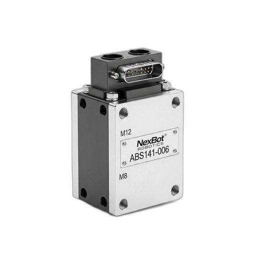
Role of the Component: High-resolution encoders, such as the NexBot Drives ABS141-006 Absolute Encoder, are crucial for tracking the exact position of each robotic joint, even after a power cycle. With features like 24-bit single-turn resolution, they provide the granular data needed for high-precision tasks. Its IP67 rating indicates a design meant to withstand dust and moisture, but regular maintenance is still vital.
Preventive Maintenance Checklist:
- Visual Inspection: Regularly inspect the encoder housing for any signs of physical damage, such as cracks, dents, or loose fittings. Ensure mounting bolts are secure and have not loosened due to vibration.
- Seal Integrity: For encoders operating in harsh environments, verify the integrity of shaft seals and connector gaskets. The IP67 rating is only effective if the seals are not compromised. Look for signs of moisture ingress or particulate buildup around connection points.
- Cabling and Connections: Examine the cable running from the encoder to the drive. Look for chafing, kinks, or insulation damage. Ensure the connector is securely fastened and free of corrosion.
- Performance Monitoring: During operation, monitor the joint for any signs of jitter, hesitation, or 'hunting' for position. These can be early indicators of encoder signal degradation. Use diagnostic software to check for fault codes or an increase in signal noise.
Common Wear Indicators:
- An increase in positioning errors or a loss of repeatability.
- Fault codes related to 'position feedback error' or 'encoder signal loss'.
- Audible noise from the joint's motor as it struggles to maintain position due to a noisy signal.
Ensuring Robust Communication: Fieldbus Connectors
Modern robotic systems are complex networks of interconnected devices. The physical layer of this network—the cables and connectors—is the foundation for all data exchange. A single loose or corroded connector can bring an entire production line to a halt.
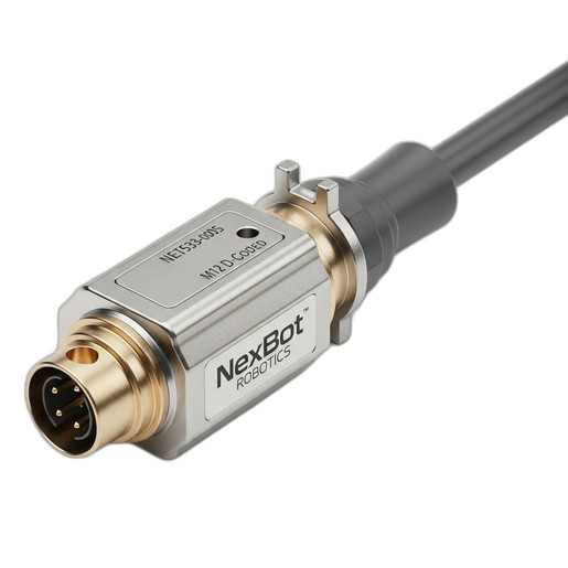
Role of the Component: Fieldbus connectors like the NexBot Robotics NET533-005 Fieldbus Connector are designed for the factory floor. Its M12 D-Coded design provides a secure, vibration-resistant connection for industrial networks like PROFINET. These connectors are the physical link between controllers, I/O blocks, sensors, and robots.
Preventive Maintenance Checklist:
- Connection Security: Physically check that all M12 connectors are properly tightened. Vibration can cause them to loosen over time, leading to intermittent connections. The threaded coupling should be snug.
- Inspect for Contamination: When a connection is accessible, disconnect it (with power off) and inspect the pins and sockets. Look for dirt, oil, metal shavings, or signs of moisture. Clean with an appropriate contact cleaner if necessary.
- Check for Pin Damage: Look for bent, broken, or pushed-in pins. Mating a connector with a damaged pin can cause a short or permanently damage both sides of the connection.
- Cable Strain Relief: Ensure that the cable leading into the connector is not under excessive strain. The weight of the cable should be supported by cable trays or clamps, not the connector itself. Check for sharp bends or kinks right at the back of the connector.
Common Wear Indicators:
- Intermittent network dropouts or devices disappearing from the network.
- An increase in communication error counters (CRC errors, dropped packets) in the network diagnostics.
- Visible corrosion (green or white powder) on the connector pins or housing.
Verifying System Integrity: Safety Controllers
Safety systems are non-negotiable. A safety controller is the brain of the robot's safety circuit, monitoring inputs from E-stops, light curtains, and door switches to ensure the system operates within safe parameters. Its maintenance is less about physical wear and more about functional verification.
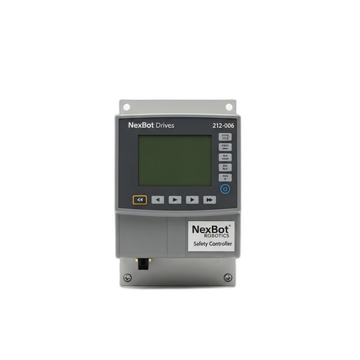
Role of the Component: A dedicated safety controller, such as the NexBot Drives 212-006 Safety Controller, manages the safety logic independently of the main robot controller. It communicates over a secure protocol like PROFIsafe over PROFINET to ensure that safety signals are transmitted reliably.
Preventive Maintenance Checklist:
- Functional Testing: This is the most critical PM task. On a regular schedule (e.g., monthly or pre-shift), test every safety input. Actuate each E-stop button, break the beam on every light curtain, and open every interlocked gate to confirm the controller correctly detects the input and places the robot in a safe state.
- Status Indicator Review: Visually inspect the LED status indicators on the controller. Familiarize yourself with the meaning of each light (e.g., Power, Run, Fault, Input/Output status). Any unexpected red or flashing amber lights should be investigated immediately.
- Review Controller Logs: If accessible, periodically review the diagnostic logs of the safety controller. Look for recurring, non-critical faults that could indicate a degrading sensor or wiring issue that hasn't yet caused a full shutdown.
- Environment Check: Ensure the controller's enclosure is clean, dry, and free of excessive dust. Verify that ventilation paths are not blocked to prevent overheating.
Common Wear Indicators:
- Nuisance trips where the safety circuit engages without a clear cause.
- Failure of the safety system to reset after a legitimate trip.
- Diagnostic fault codes pointing to specific input channels or internal errors.
By incorporating these detailed checks into your regular maintenance schedule, you shift from a reactive to a proactive stance. Addressing the small issues with encoders, connectors, and safety controllers will prevent the large-scale failures that cause significant downtime and impact your bottom line.