Automating TIG welding processes offers significant advantages in precision, consistency, and operator safety. Collaborative robots, or cobots, have made this technology more accessible than ever. This guide will walk you through the essential steps for setting up a safe and efficient collaborative TIG welding cell using key components from NexBot Robotics.
Prerequisites and Component Selection
Before you begin, a successful integration requires careful planning and the right hardware. A typical cobot TIG welding cell consists of the robot arm, end-of-arm tooling (the torch), a power source, a work area, and crucial safety systems.
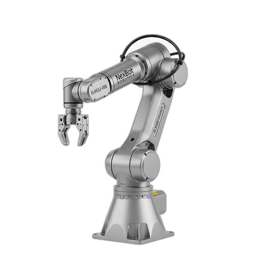
- Collaborative Robot: The foundation of your cell is the robot itself. The NexBot Robotics FLR022-005 Collaborative Robot is an excellent choice, offering a 10 kg payload capacity that easily handles a professional welding torch and a 1300 mm reach suitable for a wide range of part sizes.
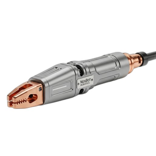
- Welding Torch: The torch is your primary tool. For demanding, high-quality welds, the NexBot Robotics TIG432-004 350A Water-Cooled TIG Torch provides the durability and thermal management needed for continuous operation, ensuring stable arc performance.
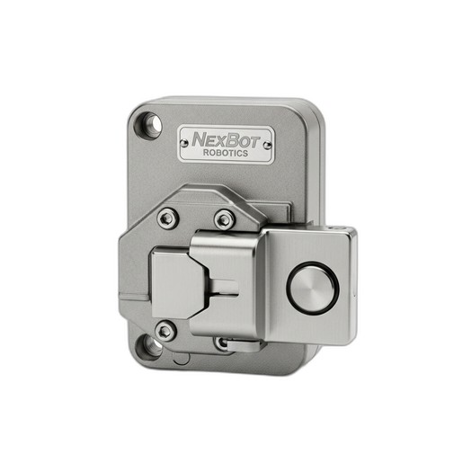
- Safety System: In any robotic application, safety is paramount. The NexBot Robotics 621-005 Door Interlock is a critical component for safeguarding the workcell, preventing access during operation.
- Additional Equipment: You will also need a compatible TIG welding power source, a sturdy workbench or fixture table, part fixtures, and a cooling unit for the water-cooled torch.
Step 1: Mechanical Integration and Workcell Layout
Proper physical setup is the first step toward a reliable system.
- Mount the Cobot: Secure the FLR022-005 cobot to a rigid, stable surface. This could be a heavy-duty steel table or a dedicated robot pedestal. Ensure the mounting surface is perfectly level to maintain accuracy. The robot's base must be bolted down according to the manufacturer's torque specifications.
- Design the Layout: Arrange the workbench, fixtures, and robot in a way that optimizes the robot's reach. The 1300 mm reach of the FLR022-005 allows for flexibility, but you should minimize unnecessary long-distance movements to improve cycle times. Ensure there is clear, safe access for an operator to load and unload parts.
- Install the TIG Torch: Mount the TIG432-004 torch to the cobot's end-of-arm flange. Use a durable, precisely machined mounting bracket. Route the torch's cables and cooling lines along the robot arm, using the provided cable management points to prevent snagging or excessive wear during movement.
Step 2: Electrical and Communication Setup
With the mechanical components in place, it's time to connect the electronics.
- Power the Robot: Connect the FLR022-005 cobot to a suitable 48VDC power supply. Ensure the power source is rated for the robot's peak current draw.
- Establish Communication: The FLR022-005 utilizes the EtherCAT protocol for high-speed, deterministic control. Connect the robot controller to your main PLC or control system via an Ethernet cable. This link will be used to send program commands and receive status feedback.
- Integrate the Welder: Connect the TIG power source to the cobot's controller I/O. This typically involves wiring signals for 'Arc On/Off' and 'Gas On/Off'. This allows the robot's program to control the welding process precisely at specific points in its path.
- Connect the Torch Cooler: Wire the water cooler for the TIG432-004 torch to a power source and ensure its control signals are integrated with the welding power source, so cooling begins when the system is active.
Step 3: Implementing Safety Systems
Collaborative does not mean the absence of risk. A thorough safety system is non-negotiable.
- Install Physical Guarding: Enclose the workcell with safety fencing to create a defined operational zone. This is especially important in TIG welding to protect personnel from arc flash and UV radiation.
- Mount the Door Interlock: Install the NexBot Robotics 621-005 Door Interlock on the access gate of the safety fence. Its robust design and 1500 N holding force prevent the door from being opened accidentally during operation.
- Wire the Safety Circuit: Connect the interlock to the robot controller's dedicated safety I/O channels. Program the controller to enter a safe-stop or emergency-stop condition immediately if the gate is opened. The solenoid-controlled guard locking feature ensures the door remains locked until the robot has completed its cycle and is in a safe state.
Step 4: Programming the Welding Path
The intuitive nature of cobots simplifies programming. The FLR022-005 can be programmed using a handheld teach pendant.
- Define the Tool Center Point (TCP): The TCP is the precise location of the tungsten electrode's tip. Accurately defining the TCP is critical for weld accuracy. Use the robot's built-in utility to define the TCP by approaching a fixed point from several different angles.
- Teach Waypoints: Manually guide the robot arm to create a series of waypoints that define the welding path. Add commands at specific points to activate the welder (Arc On) and deactivate it (Arc Off).
- Set Parameters: For each movement, define the speed, motion type (linear, joint), and precision (corner rounding). For welding segments, use linear moves to ensure a straight and consistent travel speed. Welding parameters like voltage, amperage, and gas flow are set on the power source but triggered by the robot's program.
Step 5: Calibration and Initial Testing
Never run a new program at full speed with a live arc.
- Dry Run: Execute the program at a very low speed (10-20%) without activating the welder. Watch closely to ensure the path is correct, there are no collision risks, and the cable management does not bind.
- Test Welds: Once the path is verified, perform test welds on scrap material identical to your production parts. Start with conservative welder settings and adjust them to achieve the desired bead profile and penetration.
- Refine the Program: Make small adjustments to the robot's path, speed, and torch angle to optimize the weld quality. Repeat testing until the results are consistent and meet your quality standards.
Step 6: Perform a Formal Risk Assessment
Finally, a comprehensive risk assessment is required by safety standards like ISO 13849. This formal process involves identifying all potential hazards (e.g., collision, burns, arc flash, electrical shock) and ensuring that your safety measures, including the proper function of the 621-005 interlock, effectively mitigate them to an acceptable level. Document this assessment thoroughly.
By following these steps, you can successfully integrate the NexBot Robotics FLR022-005 cobot and its associated components to create a productive, reliable, and safe automated TIG welding cell.