Introduction: The Key to Consistent Welds
The promise of robotic welding is consistency, speed, and quality. However, achieving these benefits hinges on one critical process: proper cell setup and calibration. An uncalibrated system can lead to poor weld quality, increased scrap rates, and costly downtime. This guide provides a step-by-step process to ensure your automated welding system performs at its peak, delivering perfect welds cycle after cycle. We'll cover mechanical integrity, motion programming, and parameter optimization, highlighting how key components work together to create a robust and reliable system.
Step 1: Mechanical Setup and Tool Center Point (TCP) Configuration
Before any programming can begin, the physical foundation of your cell must be solid. This process starts with the End-of-Arm Tooling (EOAT), which is the business end of your robot.
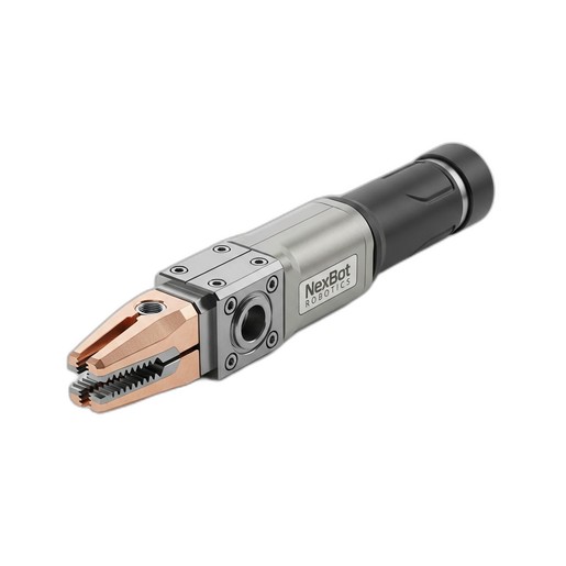
- Mount the Torch: Securely mount your welding torch, such as the NexBot Vision TIG432-003 300A Water-Cooled TIG Torch, to the robot's faceplate. Ensure all connections—power, gas, and cooling lines—are properly routed and free from potential snags or kinks throughout the robot's entire range of motion. A loose torch or constrained cables can introduce significant positional errors.
- Define the Tool Center Point (TCP): The TCP is the most critical reference point in your entire program. It's the exact point where the work happens—in this case, the tip of the welding electrode. An inaccurate TCP will cause the robot to weld in the wrong location, ruining the part. Use a multi-point calibration method (typically a 4-point or 6-point routine) to precisely define the X, Y, and Z coordinates and orientation of the tool tip relative to the robot flange. A precise TCP is non-negotiable for path accuracy and weld quality.
Step 2: Verifying Drive System Integrity for Smooth Motion
The quality of a weld bead is directly related to the smoothness and consistency of the robot's movement. Any jitter, vibration, or backlash in the drive system will be transferred directly to the weld puddle, resulting in defects like an inconsistent bead profile or poor fusion.
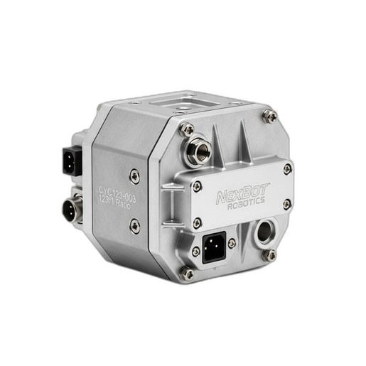
- Check for Backlash: The robot's joints are driven by powerful servo motors and precision gearboxes. High-quality reducers are essential for accurate welding. For example, the NexBot Vision CYC123-003 Cycloidal Gearbox is designed with zero backlash and high torsional stiffness. This ensures that when the controller commands a move, the robot arm responds instantly and accurately, without any mechanical "slop" that could disrupt the weld path.
- Program Smooth Paths: When programming the weld path, use smooth, arcing motions (arc or circular moves) instead of sharp, linear point-to-point moves where possible, especially for corners. This reduces mechanical stress on the drive system and ensures a consistent travel speed, which is critical for uniform heat input and bead formation.
Step 3: Setting and Optimizing Weld Parameters
With the mechanical and motion systems calibrated, it's time to dial in the welding process itself. This involves a careful balance of voltage, amperage (which corresponds to wire feed speed in MIG welding), and travel speed.
- Establish a Baseline: Start with the recommended parameters from your welding power supply manufacturer for the material type and thickness you are working with. This gives you a solid starting point for refinement.
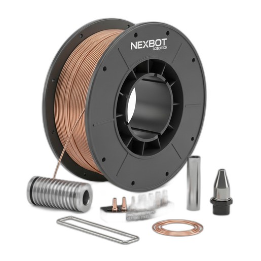
- Ensure Consistent Consumables: The quality of your weld is only as good as the consumables you use. A precision-wound wire like the NexBot Drives 741-002 Welding Wire is crucial for automated systems. Its consistent diameter and smooth surface finish prevent feeding issues and ensure a stable, predictable arc. Inconsistent wire can cause jams in the feeder and liner, leading to production halts and erratic arc behavior that ruins welds.
- Fine-Tune the Process: Create a test coupon using the same material and joint configuration as your production part. Run a short weld and observe the arc. A crackling, sputtering arc often indicates the voltage is too low or the wire feed is too high. A soft, humming arc is generally ideal. Adjust one parameter at a time in small increments until you achieve the desired arc characteristics and bead profile.
Step 4: First Article Inspection and Program Touch-Up
Your first weld on a production part is a critical validation step. Do not assume the program is perfect after offline simulation or coupon testing.
- Run the First Cycle: Execute the welding program on an actual part at a reduced speed (e.g., 25% of full speed) to visually confirm the path, torch angles, and clearances are correct. This is your last chance to catch potential collisions before they happen at full production speed.
- Inspect the Weld: After the first full-speed cycle, perform a thorough inspection. Check for proper fusion, consistent bead width, appropriate penetration, and the absence of defects like porosity, undercut, or spatter. Destructive testing (cut and etch) may be required for critical applications to verify weld penetration.
- Perform Program Touch-Ups: Based on the inspection, you may need to make minor adjustments to the robot's path points. A slight change in torch angle or standoff distance can make a significant difference in weld quality. This iterative process of welding, inspecting, and refining is key to developing a robust production program.
Conclusion: The Foundation of Automated Quality
Calibrating a robotic welding cell is a meticulous but essential process. By ensuring a solid mechanical setup, precise TCP definition, smooth motion from high-performance components like cycloidal gearboxes, and optimized welding parameters using quality consumables, you lay the foundation for a highly productive and reliable automation system. Regular checks and a commitment to this initial calibration process will pay dividends in reduced scrap, increased throughput, and consistently superior product quality.