Introduction: From Crate to Production
Deploying an industrial robot is more than just unboxing a new piece of equipment; it's about building a complete, integrated system known as a robotic work cell. A well-commissioned work cell operates efficiently, reliably, and, most importantly, safely. This guide provides a foundational, step-by-step process for taking your robot from the shipping crate to its first operational task, focusing on the core components of control, safety, and software.
Following a structured approach ensures that all hardware is correctly integrated, safety protocols are robustly implemented, and the software is configured for optimal performance. Let's begin the journey of bringing your automated solution to life.
Step 1: Hardware Installation and Physical Integration
The first phase involves physically setting up the robot and its core control components. Proper installation is the bedrock of a stable and reliable system.
- Mechanical Mounting: Securely mount the robot arm to its designated pedestal or work surface according to the manufacturer's specifications. Ensure the base is level and capable of handling the robot's dynamic loads during high-speed movements.
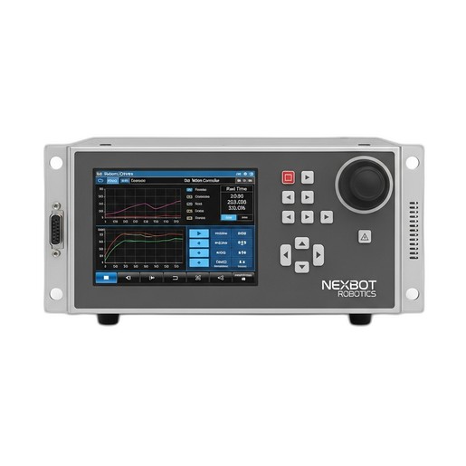
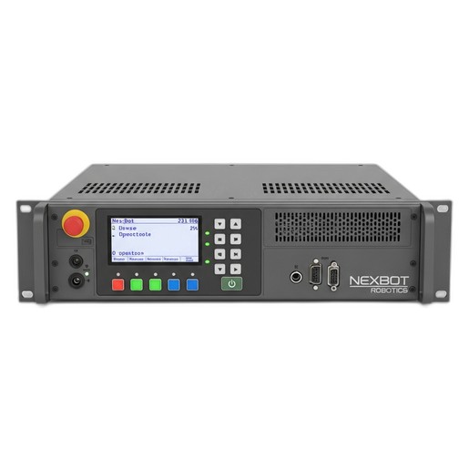
- Controller Installation: Install the brain of the operation, the motion controller. The NexBot Drives 213-006 Motion Controller is designed for this central role. Mount it in a clean, dry, and secure electrical cabinet. Connect the 24VDC power supply and the main robot communication and power cables. The 213-006's ability to provide precise, synchronized control for up to 6 axes is critical for smooth and accurate robotic motion.
- Network Connectivity: Connect the controller to your plant network. The EtherCAT protocol on the NXB-CTL-213-006 is essential for establishing high-speed, real-time communication between the controller, drives, and any I/O modules, ensuring deterministic performance for demanding applications.
- End-of-Arm Tooling (EOAT): Attach the gripper, welder, or other tool to the robot's wrist flange. Connect any necessary pneumatic lines or electrical cables for the tool, routing them carefully along the robot arm to prevent snagging.
Step 2: Implementing a Robust Safety System
Safety is not an afterthought; it is an integral part of the design and commissioning process. Before applying full power, you must establish a secure operating environment.
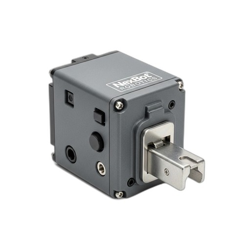
A primary component of this is safeguarding access points. The NexBot Robotics 621-007 Door Interlock is a critical device for this purpose. This PLe/SIL3 rated component ensures that the robot's power is cut or it enters a safe-stop condition the moment a cell door is opened.
Installation Process:
- Mount the interlock's sensor and actuator on the access gate and frame.
- Wire the interlock into your safety circuit. This circuit typically runs through an external safety relay or a safety PLC, which in turn controls the main power contactors for the robot's motors.
- Connect the interlock's status signals to the NexBot Drives 213-006 Motion Controller's I/O. This allows the robot program to know the state of the gate (open or closed) and respond accordingly.
- Install emergency stop buttons (E-stops) at key operator stations and wire them into the same safety circuit.
Step 3: Software Setup and System Configuration
With the hardware in place, it's time to bring the system to life through software. This stage involves establishing communication and defining the robot's virtual environment.
- Install Programming Software: On your engineering laptop or PC, install the primary programming environment. This requires a valid license, such as the NexBot Drives 231-006 Programming Software License, which unlocks the full suite of tools for development, diagnostics, and maintenance planning.
- Establish Communication: Launch the software and create a new project. Use the software's communication tools to connect to the NexBot Drives 213-006 Motion Controller over the network. Once connected, you should be able to see the controller's status in real-time.
- Configure the Robot Model: Select the correct robot model from the software's library. This loads the appropriate kinematic parameters, axis limits, and dynamic properties, which are essential for accurate motion planning.
- Define Tool and User Frames:
- Tool Center Point (TCP): Define the TCP, which is the exact point on your end-of-arm tool that will interact with the workpiece. Accurate TCP definition is crucial for precise positioning.
- User Frames: Define coordinate systems relative to your jigs, fixtures, or work surfaces. This allows you to program positions based on the workpiece rather than the robot's base, simplifying programming significantly.
Step 4: Programming Basic Motion and Logic
Now for the exciting part: teaching the robot to move. Start with a simple, fundamental task like a pick-and-place routine.
- Jogging the Robot: Using the teach pendant or software interface, carefully move the robot manually to different positions. Always do this at a low speed (typically 10% or less) during initial programming.
- Creating Waypoints: Move the robot to the 'pick' position and record the point. Move it to a safe intermediate point above the workpiece and record it. Finally, move it to the 'place' position and record that point. These recorded waypoints form the basis of your motion path.
- Writing the Program: Use the programming environment to stitch these points together into a sequence. For example:
MOVE to Approach_PickMOVE to Pick_PositionLOGIC: Close GripperMOVE to Approach_PickMOVE to Approach_PlaceMOVE to Place_PositionLOGIC: Open GripperMOVE to Approach_Place
Step 5: Testing, Validation, and Optimization
The final step is to thoroughly test your work before putting the cell into production.
- Dry Run Testing: Run the program step-by-step at a very low speed without any parts. Watch for any potential collisions, jerky movements, or unexpected paths.
- Safety System Validation: This is a critical check. With the robot running, open the access gate. The NexBot Robotics 621-007 Door Interlock should immediately signal the safety circuit to stop the robot. Test all E-stops to ensure they function as expected. Document these tests as part of your risk assessment.
- Production Trial: Introduce parts and run the cycle. Check for placement accuracy and repeatability. Use the diagnostic features of the NexBot Drives 231-006 Programming Software to monitor cycle times and axis performance.
- Optimization: Gradually increase the robot's speed to the desired production rate, ensuring that motion remains smooth and accurate. Fine-tune waypoint positions and motion types (e.g., linear vs. joint moves) to shave seconds off the cycle time while maintaining stability.
Conclusion
Commissioning a robotic work cell is a methodical process that combines mechanical installation, electrical integration, safety engineering, and software programming. By carefully following these steps and utilizing integrated components like the NexBot 213-006 motion controller, 621-007 safety interlock, and 231-006 programming software, you can build a foundation for a successful, efficient, and safe automation system.