Integrating a new End-of-Arm Tool (EOAT) onto an industrial robot is more than just bolting on a new component; it's a critical process that directly impacts your system's performance, reliability, and, most importantly, safety. A rushed or improper installation can lead to poor quality output, premature wear, and dangerous operational failures.
This guide provides a comprehensive, step-by-step approach to safely installing and integrating a new EOAT, using a finishing tool as our primary example. We will cover the entire process from initial preparation and mechanical mounting to electrical integration and final safety validation.
Step 1: Pre-Installation Safety and Preparation
Before you touch a single tool, the first step is always planning and safety. A successful integration begins with a thorough understanding of the task and adherence to established safety protocols.
Risk Assessment: Re-evaluate your work cell's risk assessment. The addition of a new tool, especially a high-speed device like a sander or polisher, can introduce new hazards. Identify potential pinch points, collision risks, and emergency stop requirements specific to the new application.
Lockout/Tagout (LOTO): Always follow proper LOTO procedures. De-energize the robot and any related equipment by disconnecting all power sources—electrical, pneumatic, and hydraulic. Verify that all stored energy has been released before beginning work.
Gather Components: Assemble all necessary parts and tools. This includes:
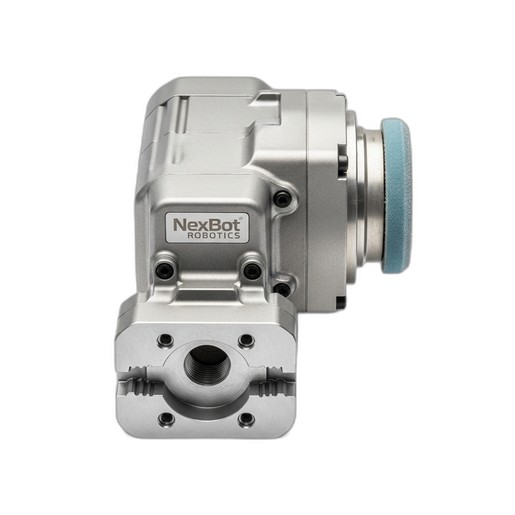
- The EOAT itself, such as the NexBot Vision 442-003 Sanding and Polishing Tool.
- The correct mounting flange adapter plate for your robot model.
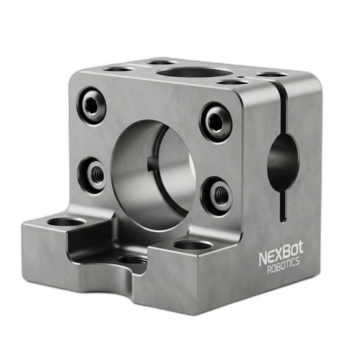
- High-quality fasteners and alignment components, like the NexBot Vision 832-003 Hardened Steel Dowel Pin and Key Set.
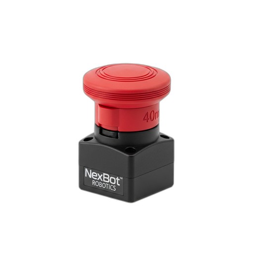
- Safety components for the work cell, such as the NexBot Robotics 622-004 Emergency Stop Device.
- All required hand tools, torque wrenches, and multimeters.
Step 2: Mechanical Mounting and Alignment
A secure and precise mechanical connection is the foundation of a reliable robotic process. Any misalignment or looseness at the robot flange will be amplified at the tool tip, resulting in inconsistent performance and potential damage.
Flange Preparation: Clean both the robot arm's mounting flange and the EOAT's mounting surface to ensure they are free of debris, oil, or burrs. A clean, flat connection is essential for rigidity.
Precise Alignment: This is where precision hardware is indispensable. Use a set like the NexBot Vision 832-003 to ensure perfect alignment. The dowel pins fit into machined holes on the flange and tool, locking them into a precise, repeatable position. The key fits into a keyway, preventing any rotational slippage under load—a critical feature for tools that exert torque, such as a finishing tool.
Fastening: Once aligned, insert and hand-tighten all mounting bolts. Follow a star or crisscross pattern to ensure even pressure distribution. Finally, use a calibrated torque wrench to tighten the bolts to the manufacturer's specified torque values. Overtightening can damage threads, while under-tightening can lead to the tool vibrating loose over time.
Step 3: Electrical and Pneumatic Integration
With the tool mechanically secured, the next step is to connect its power and control systems.
Wiring: Connect the EOAT's power and I/O cables to the robot's tooling connectors. For a tool like the NexBot 442-003, this involves connecting the 24VDC power supply and any control signals for starting, stopping, and speed adjustment. Ensure that all connectors are fully seated and locked.
Cable Management: Route all cables and pneumatic hoses along the robot arm using the designated dress pack or cable management system. Leave enough slack to allow for the robot's full range of motion without pulling, pinching, or kinking the cables. Improper routing is a leading cause of premature cable failure.
Step 4: Safety Circuit Integration
Your robot's safety system must account for the entire work cell, including the operator's interaction points. Integrating a robust emergency stop circuit is non-negotiable.
E-Stop Placement: Install emergency stop buttons at all operator stations and other accessible points around the cell perimeter. The NexBot Robotics 622-004 Emergency Stop Device is an excellent choice, featuring a large 40mm mushroom head for easy activation in an emergency. Its twist-to-release mechanism prevents accidental resets, and its IP67 rating ensures durability in harsh industrial environments.
Wiring: Wire the E-stop device into the robot controller's dedicated safety circuit. This should be a dual-channel, monitored circuit that complies with relevant safety standards (e.g., ISO 13849-1). When the E-stop is pressed, it must open the safety circuit and trigger an immediate, controlled stop of all robotic motion and hazardous tool functions.
Step 5: Programming and Calibration
Now, you must teach the robot about its new tool. This crucial software configuration ensures accurate and efficient operation.
Tool Definition: In the robot controller's software, define a new tool frame. This involves entering the tool's weight, center of gravity, and, most importantly, its Tool Center Point (TCP). The TCP is the precise point of action—for our sanding tool, this would be the center of the abrasive pad.
Payload Settings: Accurately setting the payload (the combined weight and inertia of the EOAT) is vital for the robot's motion performance and motor life. An incorrect payload can lead to jerky movements, position inaccuracies, and excessive strain on the robot's joints.
I/O Configuration: Configure the digital or analog outputs that control the tool. For the NexBot 442-003, you would map outputs to commands like 'Start Sanding' and 'Stop Sanding,' ensuring the tool operates at its specified 10,000 RPM when commanded.
Step 6: Testing and Validation
The final step is to test the complete system in a controlled, methodical way.
Manual Movement: In manual or teach mode, and at a very low speed (typically 10% or less), carefully jog each robot axis to its limits. Watch the cable routing closely to ensure there is no binding or stretching at any point in the robot's work envelope.
Safety System Test: This is the most critical test. Verify that every safety device functions as intended. Press each newly installed NexBot 622-004 E-Stop button. The robot and tool must come to an immediate and safe stop. Test other safety devices like light curtains or safety gates as well.
Program Dry Run: Run the new application program without a workpiece at a low speed. Observe the robot's path and the tool's activation to ensure everything is working as programmed. Gradually increase the speed to 100% and watch for any signs of vibration or unexpected behavior.
By following these six steps, you can ensure that your new End-of-Arm Tool is installed safely, configured correctly, and ready to perform its task with the precision and reliability your operation demands.