Industrial robots are the backbone of modern manufacturing, but their continuous operation subjects them to significant mechanical stress. The joints—axes of rotation and articulation—are particularly susceptible to wear and tear. Unscheduled downtime due to a joint failure can halt an entire production line, leading to significant financial losses. The solution is to move from reactive or even preventive maintenance to a predictive maintenance (PdM) strategy. By monitoring the health of your robot in real-time, you can detect signs of failure long before they become critical.
This guide will walk you through the process of installing a vibration sensor, a cornerstone of any effective robotic PdM program. We will cover the physical installation using appropriate hardware and discuss how to begin interpreting the data to make informed maintenance decisions, such as when to schedule an overhaul using a dedicated hardware kit.
Required Tools and Components
Before you begin, gather the necessary components and tools to ensure a smooth and safe installation. Precision is key, so using the right equipment is non-negotiable.
Components:
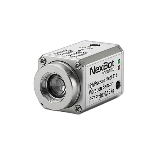
- Vibration Sensor: NexBot Robotics 342-005 Vibration Sensor (NXB-SNS-342-005). Its wide 10 Hz to 10 kHz frequency range is crucial for detecting a variety of potential faults, from low-frequency imbalances to high-frequency bearing degradation.
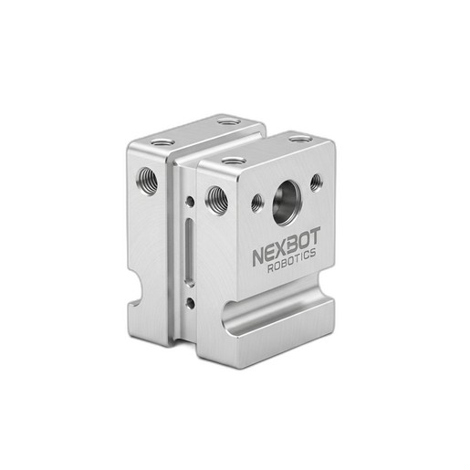
- Mounting Bracket: NexBot Robotics 812-005 Sensor Mounting Bracket (NXB-SNS-812-005). This bracket is designed for a secure, rigid fit to ensure data accuracy.
- IO-Link Master: A compatible IO-Link master to connect the sensor to your PLC or control system.
Tools & Safety Gear:
- Personal Protective Equipment (PPE): Safety glasses, gloves.
- Torque Wrench with appropriate socket/hex bit sizes.
- Hex Key Set (Metric).
- Degreaser/Cleaning Wipes.
- Cable Ties.
Step 1: Safety First - Preparing the Robot Cell
Safety is the absolute priority. Never work on a robot while it is powered and operational.
- Notify Personnel: Inform all relevant personnel that maintenance is being performed on the robot.
- Power Down: Follow your facility's specific lockout/tagout (LOTO) procedures to completely de-energize the robot and its controller. This includes electrical, pneumatic, and hydraulic power sources.
- Verify Zero Energy: Use a voltmeter to confirm that there is no residual electrical energy in the system.
- Secure the Robot Arm: If necessary, manually move the robot arm to a safe, stable position where the target joint is accessible. Use mechanical blocks or pins if there is any risk of the arm moving due to gravity.
Step 2: Selecting the Optimal Sensor Location
The quality of your vibration data is directly dependent on the sensor's placement. The goal is to mount the sensor as close as possible to the component you want to monitor, typically a bearing housing within a major joint (e.g., Axis 2, 3, or 5, which often bear heavy dynamic loads).
- Proximity: Choose a flat, solid mounting surface on the stationary part of the joint housing.
- Path: Ensure the sensor is on the direct load path of the bearing. This ensures that the vibrations from the bearing are transmitted cleanly to the sensor.
- Orientation: Mount the sensor in an orientation that will capture the primary axis of vibration. For a rotating joint, this is often the radial or axial direction.
- Clean Surface: Thoroughly clean the selected mounting surface with a degreaser to remove any oil, grease, or debris. A clean surface is essential for rigid contact and accurate data transmission.
Step 3: Installing the Sensor Mounting Bracket
A flimsy or incorrectly installed bracket will introduce its own vibrations, corrupting your data. The NexBot Robotics 812-005 Sensor Mounting Bracket is engineered for a rigid connection.
- Position the Bracket: Place the NXB-SNS-812-005 bracket onto the cleaned surface, aligning it with the pre-existing mounting holes on the robot joint housing.
- Secure Fasteners: Loosely thread the mounting screws.
- Torque to Specification: Use a torque wrench to tighten the screws to the manufacturer's recommended torque value. This is critical for preventing the bracket from loosening over time due to the robot's own operational vibrations.
Step 4: Mounting and Connecting the Vibration Sensor
With the bracket securely in place, you can now mount the sensor itself.
- Attach the Sensor: Screw the NexBot Robotics 342-005 Vibration Sensor into the threaded hole on the mounting bracket. Tighten it firmly by hand, then give it a final tightening with a wrench as per the sensor’s installation guide (typically a quarter-turn past hand-tight) to ensure solid mechanical coupling.
- Connect the Cable: Connect the M12 connector of your IO-Link cable to the sensor. Ensure the connection is secure to maintain its IP rating.
- Route the Cable: Carefully route the cable along the robot arm, following existing cable management channels. Use cable ties to secure it, leaving enough slack around the joints to allow for the robot's full range of motion without straining the cable.
- Connect to IO-Link Master: Connect the other end of the cable to an available port on your IO-Link master, which is typically located in the robot's control cabinet.
Step 5: Integrating Sensor Data and Establishing a Baseline
Once the hardware is installed, you need to configure the sensor in your control system. The NXB-SNS-342-005 uses the IO-Link protocol, which simplifies this process.
- Configuration: Using your PLC programming software, integrate the sensor's IODD (IO Device Description) file. This file tells the IO-Link master how to communicate with the sensor and interpret its data.
- Establish a Baseline: Run the robot through its normal operational cycles under typical loads. Record the vibration data over a period of time (e.g., several hours or shifts) to establish a “healthy” baseline signature. This baseline represents the normal vibration pattern of the joint when it is in good working order.
- Set Alarms: Configure alarm thresholds in your HMI or SCADA system. A common practice is to set two levels: a 'Warning' level for when vibration exceeds the baseline by a certain percentage, and a 'Critical' level that indicates a more urgent need for inspection.
Step 6: Using Data to Plan Your Maintenance
The sensor is now your early warning system. Monitor the vibration data for trends and anomalies:
- Increased Amplitude: A general increase in vibration amplitude often indicates developing wear, imbalance, or misalignment.
- High-Frequency Spikes: Spikes in the upper frequency range (e.g., 1 kHz - 10 kHz) can be an early indicator of bearing race or ball bearing defects.
- Low-Frequency Changes: Changes in the lower frequency range (e.g., 10 Hz - 200 Hz) might suggest issues like structural looseness or gear tooth wear.
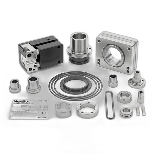
When your monitoring system flags a 'Warning' or 'Critical' alarm, it's time to act. Instead of reacting to a breakdown, you can now proactively schedule maintenance. This is where the NexBot Vision 762-003 Joint Overhaul Hardware Kit comes in. The data from the sensor tells you when to perform the overhaul, and the kit provides the high-quality components needed to do it right, including high-tensile fasteners, precision dowels, and shims to restore the joint to its original factory specifications.
By following this guide, you can successfully implement a powerful predictive maintenance strategy for your robotic assets, turning unscheduled downtime into planned, efficient servicing.