Introduction: The Critical Role of End-of-Arm Tooling
In the world of industrial robotics, the robot arm itself is only half the story. The true capability of an automated system is unlocked by its End-of-Arm Tooling (EoAT). Whether it's a gripper, a welder, or a sensor, the EoAT is what allows the robot to interact with its environment and perform its designated task. However, simply attaching a tool to the robot flange is not enough. Proper integration, configuration, and calibration are essential for achieving the precision, speed, and safety required in modern manufacturing.
A poorly integrated tool can lead to inaccurate positioning, dropped parts, premature wear, and even dangerous system failures. This guide will walk you through the fundamental steps of integrating a new EoAT, using a magnetic gripper as our primary example, to ensure your robotic cell operates at peak performance. We will cover the mechanical, electrical, and software aspects of the process, highlighting key components that ensure success.
Step 1: Pre-Installation Checklist and Safety
Before you touch a single tool, a thorough preparation phase is crucial. Rushing this step is a common mistake that can cause significant delays and safety hazards later on.
1. Verify Compatibility:
- Mechanical: Check that the EoAT's mounting pattern matches the robot's ISO flange. Adapter plates can be used but must be rigid and accurately machined.
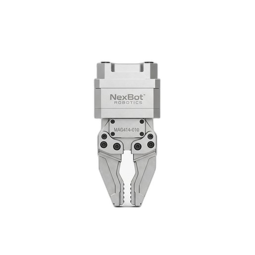
- Payload: Ensure the combined weight of the gripper and the intended part does not exceed the robot's maximum payload capacity. For example, the NexBot Robotics MAG414-010 Magnetic Gripper has a lift capacity of 10 kg, but you must also account for the gripper's own weight in the total payload calculation.
- Electrical: Confirm that the robot's I/O module can provide the required voltage and current for the tool. The MAG414-010, for instance, operates on a standard 24VDC supply.
2. Gather Tools and Documentation:
- Assemble all necessary tools: torque wrench, hex keys, screwdrivers, and any specific tools mentioned in the EoAT manual.
- Have the manuals for both the robot and the EoAT on hand. Digital copies on a tablet are often convenient.
3. Implement Safety Procedures:
- Ensure the robot is in a safe, powered-down state. Follow standard Lockout/Tagout (LOTO) procedures to prevent accidental startup.
- Verify that all sources of energy (electrical, pneumatic, hydraulic) are de-energized and bled off.
Step 2: Mechanical and Electrical Installation
With preparation complete, you can begin the physical installation.
Mechanical Mounting:
- Carefully attach the EoAT to the robot flange, ensuring it is seated correctly.
- Insert and hand-tighten all mounting bolts.
- Using a torque wrench, tighten the bolts in a star pattern to the manufacturer's specified torque value. This ensures even pressure and a secure connection, preventing any shift during high-speed movements.
Electrical Connection and Cable Management:
- Connect the EoAT's power and control cables to the appropriate terminals on the robot's I/O interface. For a simple tool like the MAG414-010, this typically involves connecting the 24VDC power and the digital I/O signal wires that control the magnet's on/off state.
- Route the cables along the robot arm. Use the robot's built-in cable management system or appropriate dress packs. Leave enough slack to allow for the robot's full range of motion without straining or pinching the cables, but not so much that they can snag on equipment.
Step 3: Software Configuration and TCP Definition
This is where you teach the robot's controller about the new tool it's holding. This step is foundational for all subsequent programming and motion accuracy.
1. Define Tool Properties:
- In the robot controller's software, navigate to the tool definition settings.
- Enter the precise weight of your EoAT. This is critical for the robot's dynamics model, affecting acceleration and motor performance.
- Input the Center of Gravity (CoG) coordinates for the tool. This is usually provided by the manufacturer. An incorrect CoG will degrade the robot's path accuracy.
2. Set the Tool Center Point (TCP):
- The TCP is the most critical point of your tool—the exact location where the work happens. For our MAG414-010 Magnetic Gripper, this would be the center of the magnetic face.
- Use the robot manufacturer's recommended method to define the TCP. This often involves using a fixed pointer in the workspace and approaching it from several different angles with the tool. The robot's software uses these points to calculate the precise X, Y, and Z offset from the robot flange.
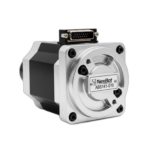
The Importance of Positional Accuracy: Defining an accurate TCP is meaningless if the robot doesn't know the exact position of its own joints. This is where high-resolution encoders are indispensable. Components like the NexBot Robotics ABS141-010 22-Bit Absolute Encoder provide the granular data needed for the robot controller to know its joint angles with extreme precision. This high fidelity is what allows the robot to place the TCP exactly where you programmed it, every single time, which is essential for tasks like placing parts in tight-fitting jigs.
Step 4: Testing and Fine-Tuning
With the tool configured, it's time to verify the setup in a controlled manner.
- Jogging and Motion Tests: In manual mode and at a very low speed, jog each robot axis to its limits to ensure the cabling does not bind or snag.
- Create a Simple Test Program: Write a basic pick-and-place routine. The program should move the robot to a known pickup point, activate the gripper, move to a drop-off point, and deactivate the gripper.
- Run and Observe:
- Execute the program one line at a time to ensure the robot follows the expected path.
- Check that the TCP aligns perfectly with the pickup and drop-off points. If there are discrepancies, you may need to re-teach your TCP.
- Verify the gripper's functionality. For the MAG414-010, test its fail-safe permanent electromagnet technology by activating it, picking a part, and then cutting power to the robot cell (following safety protocols) to confirm the part remains held.
- Iterate and Refine: Make small adjustments to the TCP and program points as needed until the robot performs the task with high repeatability. Once you are confident in the setup, gradually increase the robot's operating speed while monitoring its performance.
Conclusion: A Foundation for Success
Properly integrating End-of-Arm Tooling is a methodical process that pays dividends in performance, reliability, and safety. By following a structured approach—from pre-flight checks and careful installation to precise software configuration and thorough testing—you build a robust foundation for your automated application. High-quality components, from the gripper at the wrist to the absolute encoders within the joints, work in concert to deliver the precision modern manufacturing demands. Taking the time to get the integration right from the start will save countless hours of troubleshooting and ensure your robotic system is a productive and reliable asset for years to come.