Introduction: The Foundation of Modern Automation
Building a robotic work cell is more than just placing a robot on the factory floor. A successful implementation requires careful planning and precise integration of several key components to create a system that is safe, efficient, and reliable. From the mechanical base that defines the robot's workspace to the sensors that give it a sense of touch and the safety systems that protect personnel, each part plays a crucial role.
This guide will walk you through the fundamental steps of integrating a basic robotic work cell, focusing on three core component types: a linear rail for extended reach, a force/torque sensor for precision tasks, and an emergency stop device for essential safety. By following these steps, you can create a robust foundation for your automation projects.
Step 1: Establish the Mechanical Framework with a Linear Rail
The first step is to define the physical workspace. For applications requiring a robot to service multiple stations or handle large parts, a linear rail is indispensable. It transforms a stationary robot into a mobile unit, dramatically increasing its operational envelope.
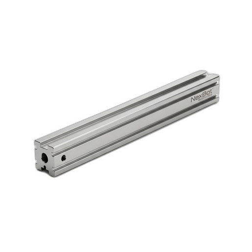
Preparation and Mounting: Begin by preparing the installation site. The floor must be level, clean, and capable of supporting the combined weight of the rail, the robot, and its maximum payload. Securely anchor the rail system, such as the NexBot Robotics 643-009 Linear Rail Track, to the floor according to manufacturer specifications. Precision is key; use a laser level to ensure the rail is perfectly straight and level along its entire length. Any deviation can lead to premature wear on the drive system and positioning inaccuracies.
Robot Installation: Once the rail is secured, mount the robot base to the rail's carriage. Ensure that all mounting bolts are torqued to the correct specification. This connection is critical for transferring forces and maintaining rigidity during high-speed movements. Proper cable management is also essential at this stage. Use appropriate cable carriers to protect robot and power cables from snagging, abrasion, and excessive bending as the robot traverses the track.
Step 2: Enhance Perception with a Force/Torque Sensor
For applications like assembly, polishing, or intricate material handling, a robot needs to do more than just follow programmed paths—it needs to feel. A 6-axis force/torque (F/T) sensor provides this crucial tactile feedback, allowing the robot to detect contact, control forces, and adapt to variations in its environment.
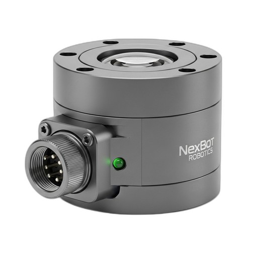
Mechanical Installation: The NexBot Robotics 311-010 6-Axis Force/Torque Sensor is typically installed between the robot's wrist flange (the end of the arm) and the end-of-arm-tooling (EOAT), such as a gripper or screwdriver. This positioning allows it to measure forces and torques exerted by the tool on the workpiece in all three dimensions (Fx, Fy, Fz) and all three rotational axes (Tx, Ty, Tz).
When mounting the sensor, ensure both the robot-side and tool-side mounting surfaces are clean and flat. Use high-grade bolts and follow the recommended tightening pattern and torque values to prevent measurement inaccuracies. The sensor's cabling should be carefully routed along the robot arm, leaving enough slack to accommodate the full range of motion without putting stress on the cable or connector. The IP67 rating of a sensor like the NXB-SNS-311-010 ensures it is protected from dust and moisture in demanding industrial environments.
Step 3: Implement Critical Safety with an E-Stop Device
Safety is the most important aspect of any robotic work cell. An emergency stop (E-Stop) device is a non-negotiable component that provides a foolproof way for personnel to bring the system to a safe state in a hazardous situation.
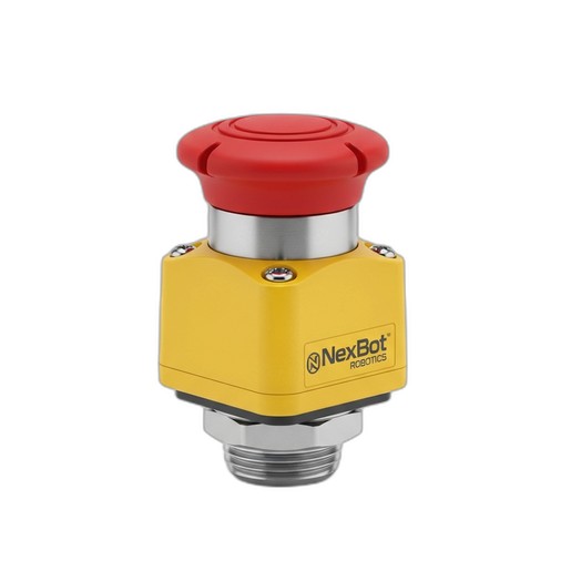
Placement and Wiring: The NexBot Vision 622-011 Twist-to-Release E-Stop Device should be installed in a prominent, easily accessible location outside of any safety fencing. Multiple E-Stops may be required for large work cells to ensure an operator can always reach one quickly.
Wiring an E-Stop correctly is critical for functional safety. The NXB-GEN-622-011 features dual-channel safety contacts, a standard for modern safety circuits. These two independent channels are wired to a safety monitoring device, such as a safety relay or a safety PLC. This redundancy ensures that the stop command will be executed even if one of the contacts fails. The E-stop circuit should be configured to remove motive power from the robot's motors and other hazardous equipment immediately upon activation, bringing the system to a controlled stop.
Step 4: System Integration and Configuration
With the hardware in place, the next step is to integrate the components into the robot's control system.
Connecting the Sensor: The NXB-SNS-311-010 sensor uses the EtherCAT protocol, a high-speed industrial Ethernet network. Connect the sensor's cable to an available EtherCAT port on the robot controller or a compatible gateway. In the robot's programming environment, you will need to configure the controller to recognize the sensor and stream its force and torque data. This data can then be used in the robot program to create logic for force-controlled movements.
Defining the External Axis: The linear rail must be configured as an 'external axis' in the robot controller software. This involves setting up the motor parameters, travel limits, and gear ratios for the rail's drive system. Once configured, the controller can coordinate the robot's arm movement with its position on the track, allowing for smooth, continuous paths across the entire workspace.
Calibration: Before operation, the F/T sensor must be calibrated. This typically involves a 'zeroing' procedure where the robot holds the tooling in a static position, and the current sensor readings are recorded as the baseline offset. This offset is then subtracted from all future measurements to ensure accurate force readings.
Step 5: Final Commissioning and Testing
The final step is to thoroughly test the entire system before putting it into production.
- Verify Safety: Test every E-Stop button in the cell. Press each one to confirm that it immediately and safely stops all robotic motion. Check that the system can only be restarted after the E-stop, like the twist-to-release NXB-GEN-622-011, has been reset and a separate start command is given.
- Test Motion: Jog the robot slowly along the full length of the linear rail to confirm smooth movement and verify that the software limits prevent any physical collisions at the ends of the track.
- Check Sensor Feedback: Create a simple test program to monitor the F/T sensor's output. Gently press on the robot's tool and verify that the sensor readings respond as expected.
By carefully following these integration steps, you can build a robotic work cell that is not only highly capable and productive but also fundamentally safe for all personnel.