Industrial robotic arms are the cornerstone of modern manufacturing, prized for their ability to perform tasks with superhuman speed and consistency. However, that precision isn't automatic. Over time, mechanical wear, environmental factors, and component drift can introduce errors, leading to decreased quality and production inefficiencies. Regular, thorough calibration is the key to maintaining peak performance.
This guide will walk you through the essential steps for calibrating an industrial robotic arm, moving beyond simple software adjustments to address the core hardware that underpins true accuracy. By understanding how mechanical components, sensors, and cabling work together, you can ensure your automation investment continues to deliver optimal results.
Pre-Calibration Checklist: Safety and Preparation
Before beginning any calibration procedure, safety is paramount. Ensure you are following all facility-specific lockout/tagout (LOTO) procedures.
Safety First:
- Power down the robot controller and disconnect the main power supply.
- Verify that all stored energy (pneumatic, hydraulic, or electrical) has been safely discharged.
- Ensure the robot's work envelope is clear of all personnel and unnecessary equipment.
Tools & Equipment:
- Manufacturer-specific calibration tool or jig
- Digital multimeter
- Torque wrenches
- Dial indicator or laser tracker for validation
- Laptop with robot controller software
- Replacement components, if inspections reveal wear
Step 1: Inspect Mechanical Drivetrain Components
Positional errors often originate in the mechanical systems that move the robot's joints. Backlash, or 'slop' in the gears and belts, is a primary culprit. A precise calibration is impossible if the underlying mechanics are compromised.
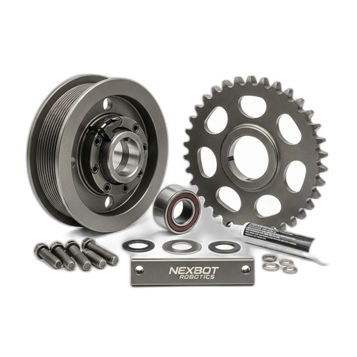
Begin by inspecting the power transmission components for each axis. This includes gearboxes, belts, and pulleys. Look for visible signs of wear, such as metal shavings, stretched belts, or worn teeth on pulleys and sprockets. For high-load applications, components like the NexBot Vision 722-003 Hardened Steel Pulley and Sprocket Set are critical. Machined from hardened steel, they offer superior wear resistance, minimizing the development of backlash over millions of cycles. Check belt tension according to the manufacturer's specifications and ensure all mounting bolts are torqued correctly. A loose pulley can introduce significant, unpredictable errors that software calibration cannot fix.
Step 2: Verify Sensor Functionality and Alignment
Accurate homing and limit detection are fundamental to a robot's ability to know its position in space. This is where proximity sensors play a vital role. These sensors establish a known, repeatable reference point (often called a 'zero position' or 'home') for each axis.
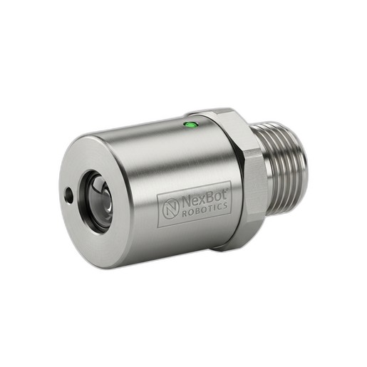
Inspect the mounting of each homing sensor. It should be secure and free from vibration. For inductive sensors like the NexBot Robotics 331-004 Inductive Proximity Sensor, verify that the sensing distance is correctly set. This M12 shielded model has a 4 mm sensing distance, and the metal flag or target that triggers it must pass within this range consistently every time the robot homes. Clean the sensor face and the target of any dirt, grease, or metal debris that could interfere with detection. Use the robot's I/O diagnostic screen to manually trigger the sensor and confirm that the controller receives the signal instantly and without flicker. The IO-Link protocol on modern sensors can also provide advanced diagnostics, alerting you to marginal signal strength before it causes a failure.
Step 3: Ensure Signal Integrity with Encoder Cables
An encoder is the robot's primary feedback device, translating the rotation of a motor into digital signals that tell the controller the exact position and velocity of each joint. The cable that carries this information is a critical link; if the signal is compromised, the robot's positional awareness is lost.
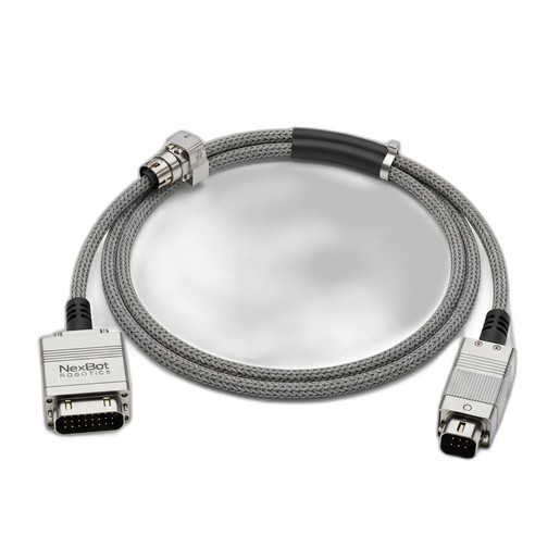
Visually inspect all encoder cables for signs of damage. Look for cuts, abrasions, or tight bends that could compromise the internal shielding or conductors. Pay special attention to the connectors at both the motor and controller ends. Ensure they are fully seated, locked, and free of corrosion. The NexBot Robotics ENC521-004 Encoder Cable is designed for industrial environments, offering robust shielding to protect against electrical noise from motors, VFDs, and other equipment. A noisy signal can introduce jitter or cause the controller to misinterpret the robot's position, leading to inaccurate movements. Using high-quality cables specified for protocols like PROFINET ensures the high-speed, error-free data transmission required for precise motion control.
Step 4: Execute the Software Calibration Routine
With the hardware verified, you can proceed to the software calibration. This process varies between robot manufacturers but generally involves using a specialized tool or jig that is mounted to the robot's end-of-arm tooling flange.
The robot is then commanded to slowly move each joint until it makes contact with specific points on the jig. The software records the encoder values at these known physical positions. This process, often called 'mastering' or 'referencing', synchronizes the encoder's digital count with the robot's actual physical geometry. This corrects for any minor assembly variations and establishes the true relationship between all the robot's links and joints.
Step 5: Test and Validate Performance
Calibration is not complete until it's validated. After mastering, define a Tool Center Point (TCP) and program the robot to move to several precise coordinates within its work envelope. Use a dial indicator, laser tracker, or vision system to measure the robot's actual final position against its commanded position. The difference is the positional accuracy.
Next, command the robot to move to the same point repeatedly from different starting positions and angles. The variation in its final position across these attempts is its repeatability. Compare these measured values against the manufacturer's specifications. If the results are within tolerance, the calibration was successful. If not, revisit the hardware inspection steps, as an underlying mechanical or electrical issue is the likely cause.