Industrial robots are powerful tools for automation, but their effectiveness is often constrained by a fundamental limitation: their fixed base. While a six-axis arm offers incredible dexterity, its operational area, or work envelope, is finite. For applications requiring access to multiple machines, long parts, or large work areas, a stationary robot simply won't suffice. The solution is to put your robot in motion.
Adding a linear rail, or a 'seventh axis', transforms a fixed robot into a mobile automation powerhouse. This guide will walk you through the key steps of integrating a linear track system, from initial design and simulation to final programming, using high-performance components to ensure precision and reliability.
Step 1: Planning and Simulation
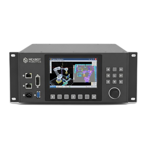
Before a single bolt is turned, successful integration begins with careful planning. The goal is to validate the concept, optimize the layout, and prevent costly rework. This is where offline programming (OLP) and simulation software become invaluable.
Using a tool like the NexBot Robotics 232-004 Simulation Software, you can create a complete digital twin of your workcell. Import your robot model, the machine or workstations it will service, and a model of the linear track, such as the NexBot Robotics 643-004 Linear Rail Track. Within this virtual environment, you can:
- Verify Reach: Confirm that the robot, mounted on the 4-meter track, can comfortably reach all required points on each machine or fixture.
- Optimize Placement: Adjust the position of the track and surrounding equipment to minimize cycle time and ensure the most efficient path of motion.
- Collision Detection: Run the entire automation sequence to identify potential collisions between the robot, the track carriage, tooling, and other cell components.
- Develop Core Programming: Create and test the robot programs offline, significantly reducing downtime on the physical system later.
This simulation phase de-risks the entire project, ensuring your hardware investment will deliver the expected performance from day one.
Step 2: Mechanical Installation and Mounting
Once the layout is finalized in simulation, the physical installation can begin. A robust and precise mechanical setup is the foundation for a reliable system.
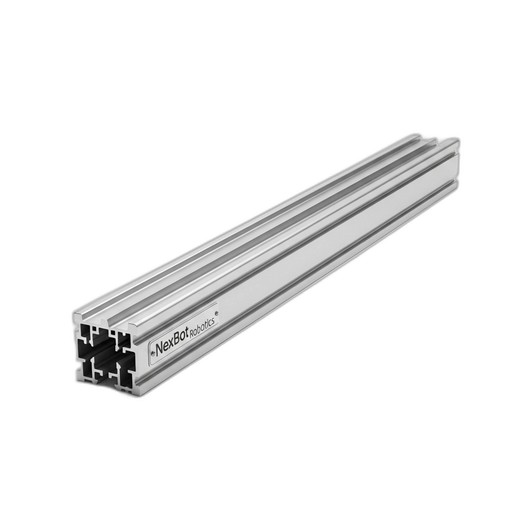
The NexBot Robotics 643-004 Linear Rail Track is designed for high-load capacity, but it must be mounted to a properly prepared surface. The floor must be level and stable enough to handle the dynamic loads of the robot moving at speed. Follow the manufacturer's guidelines for anchoring the rail system securely to the foundation.
Next, the robot itself is mounted to the carriage plate on the linear track. Ensure that the mounting adapter plate is correct for your robot model and that all fasteners are torqued to specification. Precision is key here; any misalignment can introduce stress on the system and affect positioning accuracy down the line. The high build quality of the rail system, offering ±0.05 mm repeatability, can only be fully realized with a precise installation.
Step 3: Electrical Integration and Position Feedback
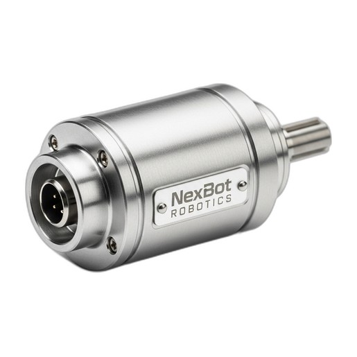
For the robot controller to command and coordinate movement along the track, it needs to know the carriage's exact position at all times. This is achieved through a servo motor and a high-resolution position feedback device, typically an incremental encoder.
The NexBot Robotics INC142-004 Incremental Encoder is ideal for this task. It provides 8192 pulses per revolution (PPR), offering the fine resolution needed for precise positioning. The encoder is mounted to the servo motor that drives the carriage along the track. As the motor turns, the encoder sends a stream of electrical pulses back to the servo drive and robot controller.
Wiring involves connecting the encoder's power (5-24VDC) and signal lines to the appropriate inputs on the external axis servo drive. Communication between the drive and the main robot controller is often handled via an industrial protocol like PROFINET, allowing for real-time, high-speed data exchange. This tight integration ensures the robot's arm movements are perfectly synchronized with its travel along the track.
Step 4: Controller Configuration and Calibration
With the hardware in place, the next step is to configure the robot controller software to recognize the linear track as an external, coordinated axis. This process typically involves:
- Defining the Axis: In the controller's configuration settings, you will add a new external axis. You'll need to input mechanical parameters like the gear ratio between the motor and the track's drive system and the linear distance traveled per motor revolution.
- Setting Travel Limits: Define the soft travel limits in the software to prevent the robot from crashing into the track's physical end-stops. These limits should be set just inside the physical boundaries.
- Homing and Calibration: The system needs a reference or 'home' position. The incremental encoder's 'Z' channel, or index pulse, is used for this. The first time the system is powered up, a homing routine is performed where the carriage moves slowly until it detects this single pulse per revolution. This position is then recorded as the zero point, from which all other positions are calculated with extreme accuracy.
Step 5: Programming and Operation
Finally, you can begin programming the robot to utilize its new seventh axis. In your robot program, movement along the track is treated just like any other axis. You can command the robot to move to a specific coordinate that includes a value for the linear track position.
For example, a program to service two machines might look like this:
- Move to home position (Arm and Track).
- Move along track to Position 1 (in front of Machine A).
- Perform tasks at Machine A.
- Move along track to Position 2 (in front of Machine B).
- Perform tasks at Machine B.
- Return to home position.
These movements can be fully coordinated, meaning the robot arm can be moving while the track carriage is also in motion, resulting in smooth, efficient 'fly-by' motions that significantly reduce cycle times.
By following these steps and using integrated components designed to work together, you can successfully extend your robot's work envelope, unlocking new levels of productivity and flexibility in your automation systems.