Introduction: The Key to Effective Automation
In the world of industrial robotics, the robot arm itself is only half the equation. The true effectiveness of an automated system often comes down to its End-of-Arm Tooling (EOAT). Among the most versatile and widely used EOATs is the pneumatic gripper, prized for its reliability, high grip force-to-weight ratio, and simplicity. However, improper installation can lead to alignment issues, premature wear, and costly downtime.
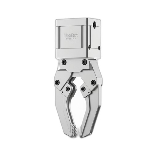
This guide provides a comprehensive, step-by-step process for correctly installing, connecting, and commissioning a pneumatic gripper on a standard industrial robot arm. By following these procedures, you can ensure your robotic cell operates safely, efficiently, and with maximum uptime. We will reference key components like the NexBot Drives PNU411-006 Pneumatic Gripper and the accessories required for a professional installation.
Prerequisites: Gathering Your Tools and Components
Before beginning the installation, it's crucial to gather all necessary components and tools. A well-prepared workspace prevents delays and ensures a smooth process. Ensure you have conducted a proper risk assessment and have the authority to perform maintenance on the robotic system.
Required Components:
- Robot Arm: A 6-axis articulated or collaborative robot with a compatible wrist flange.
- Pneumatic Gripper: For this guide, we will use the NexBot Drives PNU411-006 Pneumatic Gripper as our example.
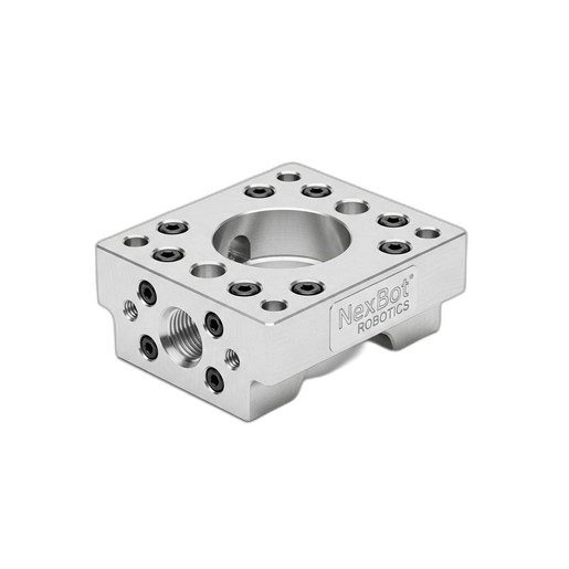
- Tool Adapter Plate: A plate that conforms to the robot's wrist mounting pattern and the gripper's mounting pattern. The NexBot Robotics 813-005 Tool Adapter Plate is ideal, featuring the standard ISO 9409-1-50-4-M6 pattern common on many robot models.
- Pneumatic System: A source of clean, dry compressed air, along with a solenoid valve, fittings, and tubing.
- Control System: A PLC or robot controller with available digital I/O for gripper actuation.
Essential Tools & Consumables:
- Safety Equipment: Safety glasses, gloves, and steel-toed boots.
- Lockout/Tagout (LOTO) Kit: To safely de-energize the robot and pneumatic systems.
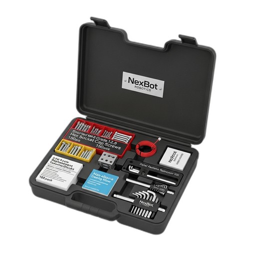
- Fasteners and Hand Tools: A quality set of hex keys and socket cap screws. The NexBot Vision 763-003 Multi-Part Maintenance Kit is invaluable here, containing Grade 12.9 hex socket cap screws, precision hex keys, and a panel fastener removal tool.
- Torque Wrench: To ensure all fasteners are tightened to specification.
- Cleaning Supplies: Non-abrasive wipes (included in the NXB-KIT-763-003) to clean mounting surfaces.
Step 1: Mechanical Mounting and Alignment
The physical connection between the robot, adapter plate, and gripper must be rigid and precise. Any misalignment can introduce stress on the robot's joints and cause inconsistent part handling.
- Safety First: Begin by executing your LOTO procedure. Power down the robot controller and shut off the main air supply to the work cell.
- Prepare Mounting Surfaces: Use non-abrasive wipes to thoroughly clean the robot's wrist flange and the surfaces of the NexBot Robotics 813-005 Tool Adapter Plate. Any debris, oil, or metal shavings can prevent a flush mount.
- Attach the Adapter Plate: Align the adapter plate with the mounting pattern on the robot's wrist. The ISO 9409-1 standard ensures compatibility, but always double-check the alignment dowel pin for a perfect fit. Insert the appropriate M6 hex socket cap screws (from your maintenance kit) and hand-tighten them in a star pattern to ensure even pressure.
- Torque to Specification: Use a calibrated torque wrench to tighten the adapter plate fasteners to the robot manufacturer's recommended specification. Overtightening can damage threads, while under-tightening can lead to vibration and loosening over time.
- Mount the Gripper: Attach the NexBot Drives PNU411-006 Pneumatic Gripper to the adapter plate. Align the mounting holes and insert the required fasteners. Again, tighten in a star pattern before applying the final torque as specified by the gripper's documentation.
Step 2: Pneumatic and Electrical Connections
With the gripper securely mounted, the next step is to provide it with power and control signals.
- Connect Air Lines: Connect the pneumatic tubing to the gripper's ports, which are typically labeled for 'open' and 'close' actions. Ensure the fittings are tightened correctly to prevent leaks but avoid over-tightening, which can damage the threads.
- Install the Solenoid Valve: Mount the solenoid valve in a protected location, often on the robot's upper arm, to minimize the length of the tubing to the gripper. This reduces actuation delay. Connect the main air supply to the valve's input port and the gripper lines to its output ports.
- Route Hoses and Wires: Carefully route the pneumatic tubing and electrical wires along the robot arm. Use the robot's integrated dress pack or appropriate cable management clips. Leave enough slack to allow for the robot's full range of motion without straining the connections. This is a critical step to prevent premature wear and failure.
- Wire the Solenoid: Connect the solenoid's 24VDC control wires to an available digital output on the robot's controller I/O block. Pay close attention to polarity (+24VDC and 0V/GND). Use the replacement terminal blocks from the NXB-KIT-763-003 if you find any existing terminals are worn or damaged.
Step 3: Software Configuration and Programming
Now, you must teach the robot controller how to operate the gripper.
- Configure I/O: In the robot's programming environment, navigate to the I/O configuration screen. Assign a name to the digital output you used for the gripper (e.g., 'Gripper_Close').
- Create Basic Functions: Program two simple subroutines or functions: one to open the gripper and one to close it.
- Close Gripper Routine: This function will set the 'Gripper_Close' digital output to HIGH (or ON).
- Open Gripper Routine: This function will set the 'Gripper_Close' digital output to LOW (or OFF).
- Add Delays: It's best practice to add a short delay (e.g., 0.2-0.5 seconds) after each command to allow the gripper's mechanical action to complete before the robot begins its next motion. This ensures a part is securely held or fully released.
Step 4: Testing and Commissioning
The final step is to safely test the entire setup.
- Power Up: Remove your LOTO devices. Power on the robot controller and slowly pressurize the pneumatic system, checking for any audible air leaks.
- Manual Test: Using the robot's teach pendant, manually toggle the 'Gripper_Close' output. Verify that the gripper actuates as expected. Check that it opens and closes smoothly without any binding.
- Programmatic Test: Run a simple test program that calls your open and close routines. Start at a very low speed (10% or less) and observe the robot and gripper. Ensure the cable and hose routing does not snag or stretch at any point in the robot's movement.
- Fine-Tuning: If your system includes a pressure regulator for the gripper, adjust it to provide the minimum force necessary to securely handle the target part. This saves energy and prevents damage to delicate objects.
Conclusion
A properly installed pneumatic gripper is a cornerstone of a productive robotic work cell. By following a structured approach—from mechanical mounting with the right adapter plate and fasteners to careful pneumatic and electrical integration and logical software setup—you create a robust and reliable system. Using high-quality components like the NexBot Drives PNU411-006 Gripper and keeping a comprehensive maintenance kit like the NexBot Vision 763-003 on hand will ensure your automation investment pays dividends for years to come through consistent performance and minimal downtime.