Introduction: The Importance of Proper EOAT Installation
End-of-Arm Tooling (EOAT) is where the real work of an industrial robot happens. Whether it's gripping, welding, or dispensing, the tool is the most critical interface between the robot and the workpiece. A pneumatic gripper, one of the most common types of EOAT, offers a powerful, reliable, and cost-effective solution for material handling. However, its performance and longevity depend entirely on a correct and secure installation.
An improper installation can lead to a host of problems, including positioning errors, premature wear, air leaks, and even catastrophic failure that can damage the robot, the product, and create a significant safety hazard. This guide will walk you through the essential steps for installing a pneumatic gripper, using the NexBot Drives PNU411-006 as our example, ensuring a safe, secure, and efficient setup for your automation cell.
Step 1: Pre-Installation Checklist and Safety
Before you touch any hardware, preparation is key. A successful installation begins with having all the right components and tools on hand and ensuring the work environment is safe.
Required Components:
- Robot Arm: Ensure the robot is in a safe, accessible position for maintenance.
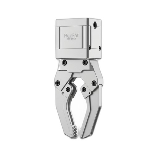
- Pneumatic Gripper: For this guide, we are using the NexBot Drives PNU411-006 Pneumatic Gripper (NXB-GEN-PNU411-006).
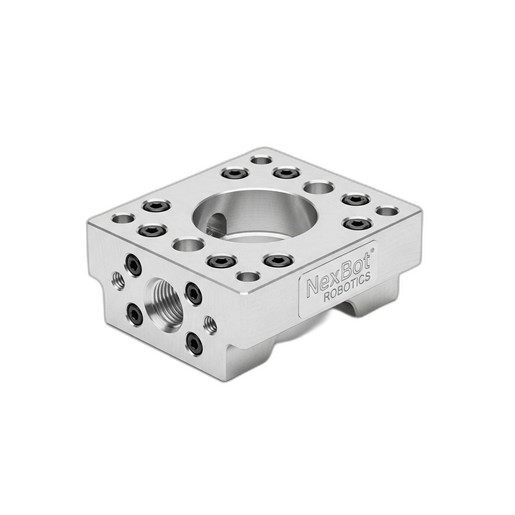
- Adapter Plate: A compatible adapter plate is crucial. The NexBot Robotics 813-005 Tool Adapter Plate (NXB-MNT-813-005) is designed for this purpose, featuring the standard ISO 9409-1-50-4-M6 pattern.
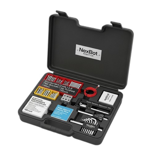
- Fasteners and Tools: You will need high-grade fasteners and the correct tools. The NexBot Vision 763-003 Multi-Part Maintenance Kit (NXB-KIT-763-003) is invaluable here, as it contains Grade 12.9 hex socket cap screws, precision hex keys, and other essentials.
- Pneumatic Fittings and Tubing: Ensure you have the correct size and type of fittings and tubing for your gripper and air supply.
- Wiring and Connectors: Appropriate wiring for the gripper's 24VDC solenoid valve.
Safety First:
- Power Down: Completely power down the robot arm and controller. Follow proper lock-out/tag-out (LOTO) procedures to prevent accidental startup.
- Vent Pneumatic System: Depressurize the pneumatic lines connected to the robot to eliminate any stored energy.
- Personal Protective Equipment (PPE): Always wear safety glasses and appropriate gloves.
Step 2: Mechanical Mounting
With safety procedures followed and components gathered, you can begin the mechanical installation. This process involves attaching the adapter plate to the robot arm and then mounting the gripper to the plate.
A. Attaching the Adapter Plate to the Robot Flange
The robot arm terminates in a standardized mounting surface called a flange. The NexBot Robotics 813-005 Tool Adapter Plate acts as the universal interface between this flange and your EOAT.
- Clean Surfaces: Use a non-abrasive wipe, like those found in the NXB-KIT-763-003, to clean the robot flange and the surface of the adapter plate. This ensures a flush, secure fit.
- Align the Plate: Align the mounting holes on the adapter plate with the threaded holes on the robot's ISO 9409-1 flange. The precision machining of the 813-005 plate ensures a perfect match.
- Secure with Fasteners: Insert the appropriate M6 Grade 12.9 hex socket cap screws from your maintenance kit. Initially, tighten them by hand in a star pattern to ensure the plate is seated evenly. Then, use a torque wrench and the correct size hex key to tighten them to the robot manufacturer's specified torque value. Using high-grade fasteners is non-negotiable for ensuring the tool remains secure under dynamic loads.
B. Mounting the Gripper to the Adapter Plate
Now that the adapter plate is secure, you can mount the NexBot Drives PNU411-006 Pneumatic Gripper.
- Align Gripper: Position the gripper onto the adapter plate, aligning its mounting holes with the threaded holes on the plate.
- Fasten the Gripper: Insert and tighten the required fasteners, again using a star pattern to ensure even pressure. Torque the fasteners to the specification provided in the gripper's documentation. Overtightening can damage the gripper housing, while under-tightening can lead to vibration and failure.
Step 3: Pneumatic and Electrical Connections
With the gripper mechanically mounted, it's time to connect the power and control systems.
A. Connecting Pneumatic Lines
- Install Fittings: Apply thread sealant to the male threads of your pneumatic fittings and install them into the 'open' and 'close' ports on the gripper. Tighten them until snug, but avoid over-tightening, which can crack the port housing.
- Connect Tubing: Connect the pneumatic tubing from your robot's air supply valves to the fittings. Ensure the lines are not kinked, twisted, or stretched. Labeling the lines can prevent confusion later.
- Leak Check: Once connected, you can briefly and carefully pressurize the system (with the robot still powered off) and check for audible or visible air leaks around the fittings. A soap and water solution can be used to spot small leaks.
B. Wiring the Electrical Control
The PNU411-006 gripper is actuated via a 24VDC signal.
- Connect Control Wires: Route the control cable from the robot's I/O block to the gripper's solenoid valve. Ensure the cable is protected from potential pinch points or abrasion as the robot moves.
- Terminate Wires: Connect the 24VDC and 0V (GND) wires to the appropriate terminals on the gripper's connector or solenoid. If you need to make fresh connections at the I/O block, the replacement terminal blocks in the NXB-KIT-763-003 are ideal for ensuring a reliable connection.
- Verify Polarity: Double-check the polarity of your connections. Reversing the polarity can damage the solenoid valve.
Step 4: System Integration and Testing
After completing the physical installation, the final step is to integrate the gripper into the robot's control software and perform a full functional test.
- Power On: Remove the LOTO device and power on the robot controller.
- Configure I/O: In the robot programming environment, configure the digital output that controls the gripper's solenoid. Assign it a clear name like 'Gripper_Open_Close'.
- Define the Tool Center Point (TCP): This is a critical step for positional accuracy. Define a new TCP that represents the center point of the gripper's fingers when holding a part. An accurate TCP is essential for the robot to place parts precisely.
- Functional Test: In manual mode and at a very low speed, toggle the digital output to actuate the gripper. Verify that it opens and closes smoothly and completely. Listen for any unusual noises or air leaks.
- Program Test: Run a simple pick-and-place routine to test the gripper under operational conditions. Observe its performance and make any necessary adjustments to air pressure or program timing.
By following these steps, you can confidently install your NexBot pneumatic gripper, ensuring it operates safely, reliably, and with the precision your application demands. Regular inspection and preventive maintenance will keep your EOAT and your entire robotic system running at peak performance.