Introduction: Building a Smarter, Safer Workcell
Integrating advanced sensors is fundamental to unlocking the full potential of industrial robotics. A well-designed system not only boosts productivity and precision but also establishes a safe operating environment for both equipment and personnel. Two critical components in this integration are safety bumpers and vision systems. A safety bumper provides essential physical contact detection, while a vision system gives the robot the 'eyes' it needs to perform complex tasks.
This guide will walk you through the essential steps to mechanically install, electrically connect, and functionally calibrate a safety bumper and a 2D vision camera in a typical robotic workcell. We will reference the NexBot Robotics 632-005 Collision Sensor Bumper and the 321-005 2D Vision Camera as practical examples of robust, integration-ready components.
Prerequisites: Tools and Components
Before beginning the installation, gather all necessary tools and components to ensure a smooth and efficient process. A well-prepared workspace is the first step toward a successful integration.
Components:
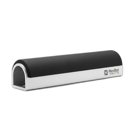
- Safety Bumper: NexBot Robotics 632-005 Collision Sensor Bumper (NXB-SNS-632-005)
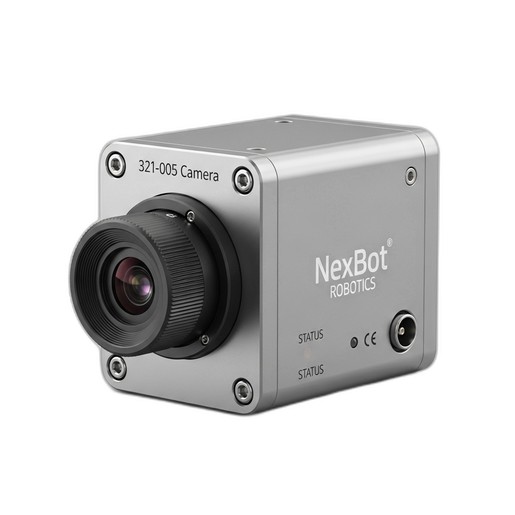
- Vision System: NexBot Robotics 321-005 2D Vision Camera (NXB-SNS-321-005)
- Robot Controller & Arm: A compatible industrial robot system.
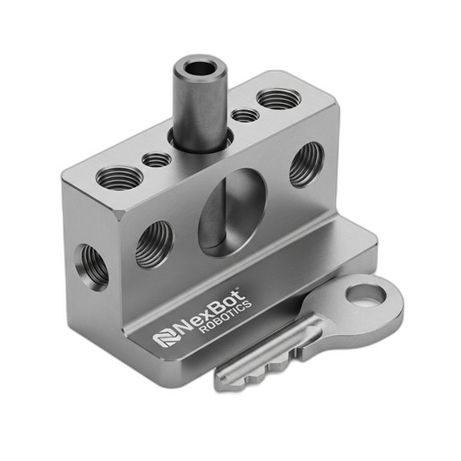
- Mounting Hardware: Appropriate brackets, screws, and fasteners. For critical alignments, consider precision hardware like the NexBot Robotics 832-004 Dowel Pin and Key Set (NXB-GEN-832-004) to prevent slippage.
- Cabling: Shielded EtherNet/IP cable, M12 connectors, and 24VDC power cables.
- IO-Link Master: If not already integrated into your robot controller's I/O block.
Tools:
- Mechanical tool set (wrenches, Allen keys, screwdrivers)
- Drill and tap set (if custom mounting holes are needed)
- Digital multimeter
- Laptop with robot programming software and camera configuration utility
- Personal Protective Equipment (PPE), including safety glasses
Step 1: Mechanical Installation
Proper mechanical mounting is crucial for sensor reliability. A poorly mounted sensor can lead to false readings, missed detections, and premature failure.
Mounting the Collision Sensor Bumper (NXB-SNS-632-005):
- Identify Impact Zones: Determine the most likely points of unintended contact on the robot's end-of-arm tooling (EOAT) or the robot arm itself.
- Fabricate Brackets: If necessary, design and fabricate sturdy mounting brackets. Ensure they do not flex under pressure.
- Secure the Bumper: Attach the NXB-SNS-632-005 bumper securely to the mounting point. Use thread-locking compound on fasteners to prevent them from loosening due to vibration.
- Verify Overtravel: The NXB-SNS-632-005 features 25 mm of overtravel for impact absorption. Confirm that the bumper has a clear path to compress and is not obstructed by other tooling or cables. This overtravel is critical for dissipating energy and protecting the robot.
Mounting the 2D Vision Camera (NXB-SNS-321-005):
- Positioning: Mount the camera in a fixed position that provides a clear, unobstructed view of the entire workspace or target area. Common mounting locations include a gantry above the workcell or a rigid post.
- Stability: The camera mount must be extremely stable and isolated from vibration. Even minor vibrations can cause image blur and reduce measurement accuracy.
- Lighting: Ensure consistent and adequate lighting across the field of view. Avoid glare and harsh shadows, which can interfere with image processing. Consider using dedicated industrial LED lighting.
Step 2: Electrical Wiring and Connectivity
Correct wiring ensures reliable communication between the sensors and the robot controller. Always follow safety procedures and de-energize the system before making electrical connections.
Wiring the Safety Bumper:
- Power: Connect a 24VDC power supply to the designated pins on the bumper's M12 connector.
- Communication: The NXB-SNS-632-005 uses the IO-Link protocol. Connect the IO-Link signal wire to a corresponding port on your IO-Link master module. This provides more than a simple on/off signal; it allows for diagnostics and sensor health monitoring.
- Safety Circuit Integration: The output from the IO-Link master must be integrated into the robot's safety circuit. This connection ensures that a bumper activation triggers a category 0 or category 1 stop, as determined by your risk assessment.
Wiring the Vision Camera:
- Power: Connect a stable 24VDC power supply to the NXB-SNS-321-005 camera.
- Communication: Connect the camera to your plant's control network using a shielded EtherNet/IP cable. Plug it into a network switch that is accessible by the robot controller. Using shielded cables is essential in electrically noisy industrial environments.
Step 3: Software Configuration
With the hardware in place, the next step is to configure the software to enable communication and define the system's behavior.
Configuring the Safety Bumper:
- IO-Link Master Setup: Using your controller's engineering software, download the IODD (IO Device Description) file for the NXB-SNS-632-005. This allows the master to recognize the bumper and its parameters.
- Robot Logic: In your robot's safety logic program, create a rule that monitors the bumper's status. When the bumper's output signal indicates a collision, program an immediate and safe stop of all robot motion. This logic is paramount for ensuring personnel and equipment safety.
Configuring the Vision Camera:
- IP Address: Assign a static IP address to the NXB-SNS-321-005 camera using its configuration utility. Ensure this address is on the same subnet as your robot controller.
- Initial Setup: Access the camera's web interface or software to configure basic settings like exposure, gain, and focus. Create a new 'job' for your specific application (e.g., part detection, barcode reading).
- Controller Integration: Add the camera as an EtherNet/IP device in your robot controller's I/O tree. This will allow the robot program to send commands to the camera (e.g., 'trigger image') and receive data back (e.g., 'part coordinates').
Step 4: System Calibration and Testing
Calibration and testing are the final, most critical steps. They validate that the entire system works together as intended.
Calibrating the Vision System:
- Robot-to-Camera Calibration: Perform a robot-to-camera calibration (also known as a world-frame or base-frame calibration). This process involves using a calibration grid or a sharp point on the robot's tool to teach the system the precise mathematical relationship between the camera's pixel coordinates and the robot's real-world Cartesian coordinates. Accuracy here is vital for precision tasks.
- Test and Refine: Program the robot to move to coordinates provided by the camera. Measure the actual position versus the target position and refine the calibration if necessary.
Testing the Safety System:
- Functional Test: With the robot moving at a slow, controlled speed, manually and gently press the safety bumper. The robot must come to an immediate halt.
- Verify Faults: Confirm that the activation of the bumper creates a fault condition on the robot's teach pendant that requires a deliberate reset procedure.
- Document: Record the results of every safety test. This documentation is a key part of your machine safety validation records and is essential for compliance.
Conclusion
A properly integrated safety and vision system transforms a standard industrial robot into a highly capable and safe automation asset. By following a structured approach to mechanical installation, electrical wiring, software configuration, and rigorous testing, you can ensure your system is reliable, accurate, and compliant with safety standards. Components like the NexBot Robotics 632-005 Collision Sensor Bumper and 321-005 2D Vision Camera are designed to simplify this process, providing robust performance and straightforward integration into modern control architectures.