Introduction: The Key to Successful Automation
Industrial robots are the backbone of modern manufacturing, but their true potential is unlocked by their End-of-Arm Tooling (EOAT). The right gripper transforms a powerful robot arm from a versatile machine into a specialized, high-performance system. For handling non-porous items like glass panes, sheet metal, or plastic casings, vacuum grippers are an industry standard, offering speed and reliability.
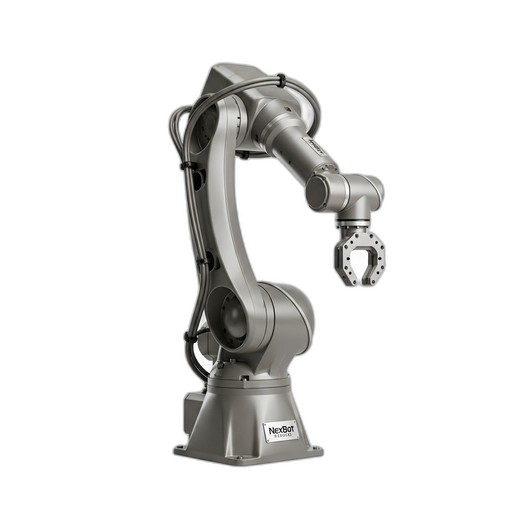
This guide provides a step-by-step process for installing, connecting, and configuring a vacuum gripper on a 6-axis industrial robot. We will use the NexBot Robotics SA011-001 6-Axis Robot Arm and the NexBot Robotics VAC413-001 Vacuum Gripper as our reference hardware, demonstrating a common and effective automation pairing.
Prerequisites: What You'll Need
Before you begin, gather the necessary components and ensure you have a safe working environment.
- Robot Arm: NexBot Robotics SA011-001 or a similar 6-axis arm with accessible tool I/O ports.
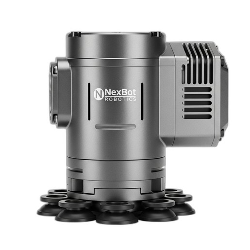
- Vacuum Gripper: NexBot Robotics VAC413-001 with integrated generator.
- Mounting Hardware: Appropriate bolts and an adapter plate if the tool flange patterns do not match directly.
- Cabling: An M12 5-pin or similar cable for power and IO-Link communication.
- Tools: Torque wrench, hex key set, and any tools specified by the robot manufacturer.
- Safety Equipment: Safety glasses, gloves, and adherence to all facility lockout/tagout procedures.
- Software: Access to the robot controller's programming interface.
Step 1: Mechanical Installation
The first step is to securely mount the gripper to the robot's tool flange, located at the end of Axis 6. A solid mechanical connection is critical for precision and to prevent vibration during high-speed movements.
- Safety First: Ensure the robot is powered down and in a safe, de-energized state according to your facility's safety protocols.
- Inspect the Flange: Check the mounting flange on the SA011-001 arm and the corresponding pattern on the VAC413-001 gripper. Most industrial robots and tools adhere to standards like ISO 9409-1, which simplifies compatibility. If the patterns differ, an adapter plate is required.
- Attach the Gripper: Align the gripper with the tool flange, using a dowel pin for precise orientation if available. Insert the mounting bolts and hand-tighten them in a star pattern to ensure the gripper sits flush against the flange.
- Torque to Spec: Use a torque wrench to tighten the bolts to the manufacturer's specified torque value. Overtightening can damage the threads, while under-tightening can lead to tool slippage and inaccurate positioning.
Step 2: Electrical Connection and Communication
With the gripper mounted, the next step is to connect it to the robot's power and control system. The VAC413-001 uses a 24VDC supply and communicates via IO-Link, a powerful protocol for smart devices.
- Locate Tool I/O: Identify the tool I/O port on the robot arm, typically located on or near Axis 6.
- Connect the Cable: Connect the appropriate M12 cable from the VAC413-001 gripper to the robot's tool I/O port. Ensure the connector is fully seated and secured.
- Verify Pinout: Confirm that the robot's tool port provides the correct 24VDC power and that the IO-Link communication pin is correctly mapped. Consult the manuals for both the SA011-001 arm and the VAC413-001 gripper to verify the pin assignments.
- Configure IO-Link Master: In the robot controller software, configure the port as an IO-Link master. You will likely need to install the gripper's IODD (IO Device Description) file, which tells the controller how to communicate with the device, what data it provides, and which parameters can be set.
The benefit of IO-Link is significant. It provides not just on/off control but also diagnostic data like vacuum level, cycle counts, and operating temperature, enabling predictive maintenance and advanced process control.
Step 3: Software Configuration - TCP and Payload
For the robot to move the gripper accurately, you must define its physical properties in the controller software. The two most critical parameters are the Tool Center Point (TCP) and the payload.
Defining the Tool Center Point (TCP): The TCP is the focal point of the tool—for a vacuum gripper, this is typically the center of the gripping surface. An accurate TCP is essential for the robot to position the picked part correctly.
- Access the TCP Utility: Navigate to the tool definition or TCP calibration screen in your robot's programming environment.
- Use the 4-Point Method: A common method involves jogging the robot to touch a fixed, sharp point in your workspace with the tool from four different angles. The controller uses these positions to calculate the exact X, Y, and Z location of the TCP relative to the robot's tool flange.
- Save the TCP: Once calculated, save the new TCP with a descriptive name (e.g., "VacuumGripper").
Setting the Payload: The robot's motion controller needs to know the weight and center of gravity of the attached payload to optimize acceleration and maintain accuracy.
- Calculate Total Mass: The payload is the mass of the gripper plus the mass of the heaviest part it will handle. The NexBot SA011-001 has a 10 kg payload capacity. While the VAC413-001 can lift up to 15 kg, you must not exceed the robot's 10 kg limit for the combined gripper and part weight.
- Enter Payload Data: Input the total mass and center of gravity coordinates into the robot's payload settings. If the exact center of gravity is unknown, an estimate is better than leaving it at zero.
Step 4: Basic Programming and Testing
Now it's time to write a simple program to test the gripper's function.
- Create a New Program: Start a new routine in the robot controller.
- Program Pick Sequence:
- Move to an 'approach' position above the target part.
- Move linearly down to the 'pick' position.
- Activate the gripper by setting the digital output or IO-Link process data bit that controls the vacuum generator.
- Add a short wait or, ideally, monitor the IO-Link input data for a 'vacuum achieved' signal.
- Move linearly up, away from the surface.
- Program Place Sequence:
- Move to an 'approach' position above the drop-off location.
- Move linearly down to the 'place' position.
- Deactivate the vacuum. This typically involves turning off the generator and briefly activating a blow-off valve to ensure a quick release.
- Move linearly up from the part.
- Test Slowly: Run your program at a very low speed, using the teach pendant to step through each command. Verify that the gripper activates, picks the part securely, and releases it correctly before increasing the speed.
Maintenance and Long-Term Reliability
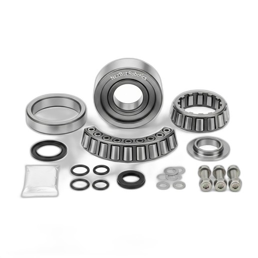
Proper integration is just the beginning. To ensure long-term performance, periodically inspect the vacuum cups for wear, cracks, or loss of flexibility. Clean the filter on the vacuum generator to prevent debris from impeding performance. This routine EOAT maintenance, combined with scheduled checks of core robot components like the NexBot Robotics 711-001 Joint Bearings, is essential for maintaining the precision and extending the service life of your entire automation cell.