Introduction: The Power of Touch in Robotics
In modern manufacturing, industrial robots are moving beyond simple pick-and-place operations. Tasks like intricate assembly, high-tolerance grinding, and delicate material handling require a level of finesse that mimics a human's sense of touch. This is where 6-axis force/torque (F/T) sensors come in, providing the robot with critical tactile feedback. Integrating one of these powerful sensors can dramatically improve process control, product quality, and operational flexibility.
However, a successful integration is more than just bolting on a new component. It requires careful planning, precise physical installation, proper software configuration, and a robust safety strategy. This guide will walk you through the essential steps to add a high-resolution sensor, like the NexBot Robotics 311-001, to your robotic system, ensuring a safe, reliable, and high-performance upgrade.
Step 1: Pre-Installation Planning and Safety Assessment
Before you touch any hardware, a thorough plan is paramount. The first consideration must always be safety. Adding a sensor that allows the robot to interact with its environment in new ways introduces new potential hazards. A comprehensive risk assessment is non-negotiable.
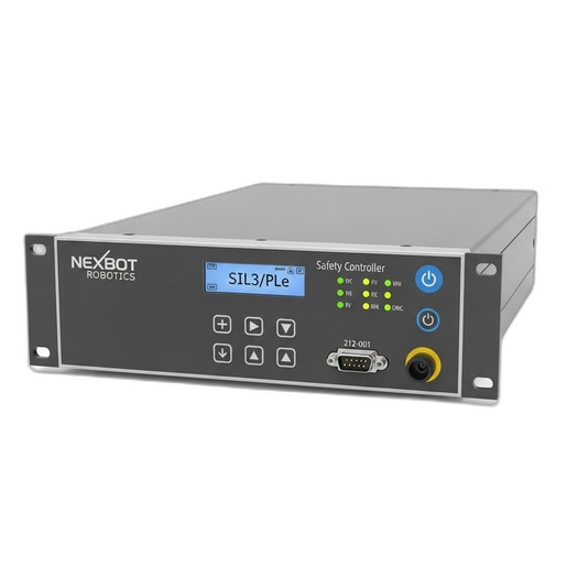
This is where a dedicated safety controller becomes the brain of your operation. The NexBot Robotics 212-001 Safety Controller (SIL3/PLe) is designed for this purpose. Your initial planning should involve:
- Risk Identification: What new risks does force-sensitive operation introduce? Consider potential crushing, shearing, or impact hazards if force limits are exceeded.
- Defining Safety Functions: Determine what should happen when an unexpected force is detected. This could be a Safety-Rated Monitored Stop (SMS), a Safe Stop 1 (SS1), or another protective measure. For example, if the force exceeds a pre-defined threshold during an insertion task, the system must halt safely.
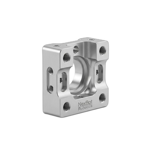
- Component Selection: Ensure all components are compatible. Verify that your robot flange pattern matches your chosen mounting hardware, such as the NexBot Servo Mounting Bracket for R-20 (NXB-MNT-SRV-R20), and that your network architecture supports the necessary protocols.
By planning your safety logic with a controller like the NXB-CTL-212-001 upfront, you create a foundation for a secure system before introducing new physical capabilities.
Step 2: Physical Installation of the Sensor and Bracket
With a solid plan in place, you can proceed with the mechanical installation. Precision here is key to accurate sensor readings.
- Power Down and Lock Out: Always follow standard lockout/tagout (LOTO) procedures before working on any robotic hardware.
- Mount the Bracket: Securely attach the NXB-MNT-SRV-R20 mounting bracket to the robot's tool flange. Use a torque wrench to tighten the bolts to the manufacturer's specifications. A rigid, properly torqued connection is essential to prevent measurement errors caused by mechanical play.
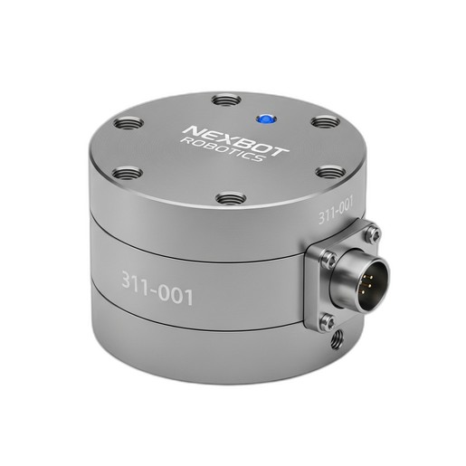
- Attach the F/T Sensor: Mount the NexBot Robotics 311-001 6-Axis F/T Sensor to the bracket. The NXB-SNS-311-001 is IP67-rated, making it suitable for environments where dust or liquids are present. Ensure the orientation of the sensor's coordinate system (X, Y, Z) aligns with your programming needs.
- Cable Management: Route the sensor's cable along the robot arm, using the existing dress pack or cable guides. Ensure there is enough slack for the robot to move through its full range of motion without straining or pinching the cable. Secure the cable to prevent snagging during operation.
Step 3: Electrical Integration and Communication Setup
Once the sensor is physically mounted, it's time to connect it to the robot controller and safety system.
The NXB-SNS-311-001 sensor operates on 24VDC and communicates via EtherCAT. EtherCAT is an ideal protocol for this application due to its high speed and deterministic, real-time data transmission, which is crucial for responsive force control.
- Power Connection: Connect the sensor to a stable 24VDC power supply as specified in its datasheet.
- Network Connection: Integrate the sensor into your EtherCAT network. This typically involves connecting it to an EtherCAT master port on your robot controller or a dedicated industrial PC. Install the appropriate device description file (ESI file) so the master can recognize and communicate with the sensor.
- Safety Controller Integration: Connect the NXB-CTL-212-001 Safety Controller to your safety network. This controller utilizes Fail Safe over EtherCAT (FSoE), allowing safety signals to be transmitted over the same EtherCAT network as your standard control data, simplifying wiring while maintaining the highest safety standards (SIL3/PLe).
Step 4: Sensor Configuration and Programming
With the hardware connected, the next step is to configure the sensor and integrate its data into your robot's program.
- Tool Center Point (TCP) Definition: The addition of the bracket and sensor changes the robot's TCP. Accurately define the new TCP, including its weight and center of gravity. Most robot programming environments have a utility for this. An accurate TCP is vital for precise motion.
- Sensor Biasing (Zeroing): Before use, the sensor must be biased or zeroed. With the end-of-arm tooling (EOAT) attached, record the sensor's readings. This baseline measurement, which accounts for the weight of the tool, is then subtracted from all subsequent readings, ensuring you are only measuring external forces applied during the operation.
- Programming Force-Guided Motion: Begin programming your application. Instead of relying solely on position-based commands, you can now use force-based commands. For example:
- Assembly:
Move until Force Z > 100Nfor a press-fit operation. - Polishing:
Maintain constant Force Z of 50N while moving along pathfor a consistent finish. - Contour Following: Use force feedback in X and Y to guide the tool along an irregular surface.
The high-resolution data from the NXB-SNS-311-001 allows for incredibly nuanced control, opening the door to applications that were previously impossible to automate reliably.
Step 5: Implementing and Validating Safety Functions
Finally, loop back to the safety plan you created in Step 1. Using the logic programmed into your NXB-CTL-212-001 Safety Controller, you will now implement and test the safety functions.
- Set Force Limits: Configure safety logic that monitors the data from the F/T sensor. For example, if the force along any axis exceeds a defined safe limit (e.g., 500N for the NXB-SNS-311-001), the safety controller should trigger a protective stop.
- Test and Validate: This is the most critical phase. Systematically test every safety function. Intentionally trigger the force limits in a controlled manner to ensure the robot stops as expected. Test emergency stops and other safety I/O. Document all validation results as required by safety standards like ISO 13849.
By integrating the F/T sensor data directly into your certified safety controller, you create an active safety system that responds dynamically to physical interactions, providing a much higher level of protection than simple positional monitoring.
Conclusion
Integrating a 6-axis force/torque sensor transforms an industrial robot from a simple positioning device into a sophisticated tool capable of delicate and complex tasks. By following a structured approach—from safety planning and precise mechanical installation to network configuration and thorough validation—you can successfully unlock these advanced capabilities. High-quality components like the NexBot 311-001 sensor, a robust NXB-MNT-SRV-R20 bracket, and a certified NXB-CTL-212-001 safety controller work together to form a cohesive system that delivers both high performance and uncompromising safety.