Integrating a heavy-payload industrial robot into a production line can seem daunting, but it's a transformative step towards greater efficiency, safety, and throughput. Robots designed for heavy lifting, such as those capable of handling 250 kg or more, can take on the most physically demanding tasks, from machine tending and palletizing to large-part assembly. A successful integration, however, hinges on a methodical approach that covers everything from foundational planning to final safety checks.
This guide will walk you through the key phases of integrating a heavy-payload articulated robot, using the capabilities of a system like the NexBot Robotics HA014-005 as a practical example.
Phase 1: Planning and Site Preparation
Before a single bolt is turned, a thorough planning phase is critical. This ensures the robot, workcell, and facility are prepared for a seamless installation.
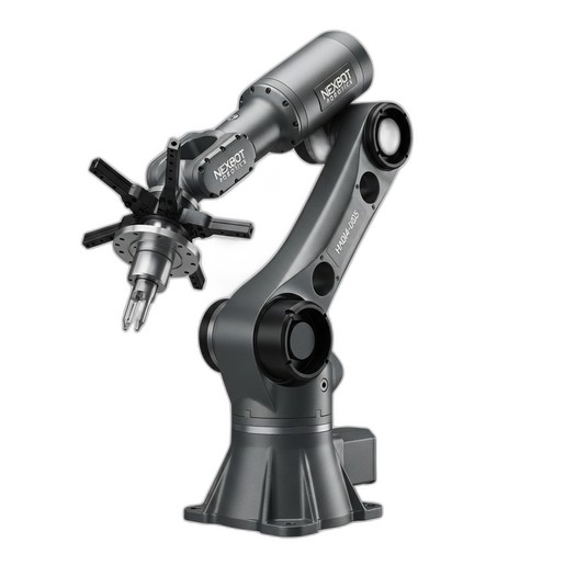
- Task Analysis & Robot Selection: Define the exact task the robot will perform. Consider payload, reach, speed, and cycle time requirements. For tasks like moving large castings or tending CNC machines, a robot with a substantial reach, like 3,100 mm, and a high payload capacity is essential. The NexBot Robotics HA014-005 is engineered for these exact applications, handling up to 250 kg with precision.
- Workcell Layout & Foundation: Map out the entire robotic workcell, including the robot's placement, safety fencing, controller cabinet, and part-feeding systems. Heavy-payload robots exert significant dynamic forces. The concrete floor must meet strict thickness and levelness specifications provided by the manufacturer to ensure stability and prevent vibration-induced errors. An engineering review of the foundation is non-negotiable.
- Power and Utilities: Verify that your facility can supply the required electrical power. High-capacity systems often require 480VAC three-phase power. Plan the routing of power and communication cables from the main panel to the robot controller, ensuring they are protected from physical damage.
- Risk Assessment: Perform a comprehensive risk assessment in accordance with industry safety standards. Identify all potential hazards and plan for mitigation measures like light curtains, safety scanners, and physical barriers. This is a foundational step for a safe and compliant system.
Phase 2: Mechanical and Electrical Installation
With the site prepared, the physical installation can begin. This phase requires precision and adherence to manufacturer guidelines.
- Robot Mounting: Carefully lift and position the robot onto its designated mounting location. Use a certified crane and rigging equipment rated for the robot's weight. Secure the robot base using the specified grade and size of anchor bolts, torqued to the manufacturer's exact values. The robot must be perfectly level to ensure accurate movement across its entire work envelope.
- Controller and Cabinet Setup: Install the robot controller cabinet in a clean, accessible, and climate-controlled location. Connect the main power and the heavy-duty cables that run between the controller and the robot arm. These umbilicals contain power and data lines for all six axes.
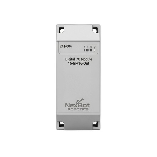
- Integrating I/O and Peripherals: Modern workcells require seamless communication between the robot and other equipment like PLCs, CNC machines, grippers, and sensors. This is managed through I/O modules. A versatile module like the NexBot Robotics 241-004 Digital I/O Module is crucial here. With 16 inputs and 16 outputs, it can handle signals for clamps, part-present sensors, and safety gate switches. Its support for EtherCAT allows for high-speed, deterministic communication within the cell.
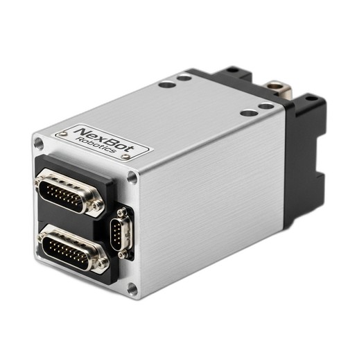
- Auxiliary Motion Control: Some applications require an external axis, such as a linear track or a complex end-of-arm tool (EOAT) with its own motor. Integrating a high-performance servo drive like the NexBot Robotics SD131-004 allows for precise control of these additional axes. This single-axis drive can be networked with the main controller, often via EtherCAT, to synchronize its motion perfectly with the robot's movements.
Phase 3: System Configuration and Programming
Once the hardware is in place, the focus shifts to software configuration and programming the robot's tasks.
- Network Setup: Establish communication between the robot controller and the wider plant network. The HA014-005 utilizes PROFINET, a common industrial Ethernet protocol, for communication with a master PLC. Meanwhile, components within the cell, like the I/O module and auxiliary servo drives, can communicate on a fast, real-time network like EtherCAT.
- Tool Center Point (TCP) and User Frame Setup: This is a critical calibration step. The TCP defines the exact point on the end-effector that will interact with the part. An accurate TCP is essential for precision. User Frames define the coordinate systems of fixtures or workstations within the cell. Properly defined frames allow the programmer to teach points relative to a fixture, so if the fixture is ever-so-slightly moved, only the frame needs to be updated, not every single point in the program.
- Path Programming: Using the robot's teach pendant, you can begin programming the motion path. Start by manually jogging the robot to key positions (waypoints) and recording them. Create a logical sequence for a simple task, such as picking a part from a conveyor and placing it in a machine chuck. Use motion types appropriate for the task—joint moves for fast transitions where the path doesn't matter, and linear or circular moves for precise paths.
Phase 4: Testing, Optimization, and Commissioning
With the initial program written, it's time for rigorous testing and optimization before going live.
- Dry Run Testing: Run the program without any parts and at a very low speed (10-25%). Carefully watch the robot's path to check for any potential collisions with fixtures, fencing, or other equipment. This is the time to catch programming errors safely.
- Cycle Time Optimization: Once you've verified the path is safe, you can gradually increase the speed. Look for opportunities to optimize the path. Can a long linear move be replaced with a faster joint move? Can corner rounding (blending) be used to smooth transitions and reduce cycle time without sacrificing accuracy?
- Safety System Validation: This is the final and most important step. Systematically test every single safety feature. Press every E-stop button. Break the beam of every light curtain. Open every gate. Confirm that each action results in the robot entering a safe-stopped condition immediately and as expected. Document these tests thoroughly.
By following this structured approach—from planning and installation to programming and safety validation—you can ensure your heavy-payload robot integration is a success. A well-integrated system will not only meet your performance targets but will also operate safely and reliably for years to come, delivering a significant return on your automation investment.