Introduction: The Building Blocks of Precise Motion
At the heart of every industrial robot is a sophisticated motion control system. This system is a symphony of components working in perfect harmony to translate digital commands into precise, repeatable physical movement. Three of the most critical players in any single axis of motion are the servo drive, the encoder, and the I/O module. The servo drive provides the power, the encoder provides the positional feedback, and the I/O module handles communication with external sensors and actuators.
Integrating these components correctly is fundamental to building a reliable and high-performance robotic system. A mistake in wiring or a misstep in configuration can lead to poor performance, system faults, or even equipment damage. This guide will walk you through the essential steps of physically installing, wiring, and configuring these core components, using NexBot Robotics products as a practical example for building a robust motion axis.
Prerequisites: Tools and Components
Before beginning the integration process, gather all necessary components and tools. A well-prepared workspace is key to a smooth and successful setup.
Core Components:
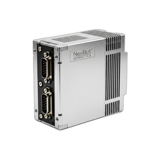
- Single-Axis Servo Drive: The muscle of the operation. We will be using the NexBot Robotics SD131-005 400V Single-Axis Servo Drive (NXB-SRV-SD131-005), which communicates via EtherCAT.
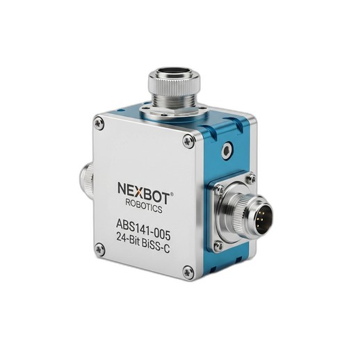
- Absolute Encoder: The eyes of the axis, providing precise position data. Our guide features the NexBot Robotics ABS141-005 Absolute Encoder (NXB-SNS-ABS141-005), offering 24-bit resolution via the BiSS-C protocol.
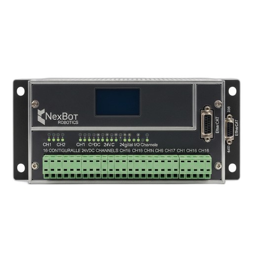
- Digital I/O Module: The system's connection to the outside world. We'll use the NexBot Robotics 241-005 Digital I/O Module (NXB-GEN-241-005) with 16 configurable channels.
- Servo Motor: A compatible 3-phase AC servo motor rated for the drive's output.
- Main Robot Controller: A PLC or industrial PC with an EtherCAT master port.
- Power Supplies: A 400-480VAC 3-phase supply for the servo drive and a separate 24VDC supply for the controller, encoder, and I/O module.
Cabling & Tools:
- Shielded motor power and encoder cables.
- Shielded EtherCAT cables (RJ45).
- Appropriate screwdrivers, wire strippers, and crimpers.
- Multimeter for verifying connections and voltages.
- Laptop with robot controller configuration software.
Step 1: Physical Installation and Wiring
Proper mounting and wiring are critical for safety and signal integrity. Always ensure all power is disconnected before making any physical connections.
- Mount Components: Securely mount the SD131-005 servo drive and the 241-005 I/O module inside a control cabinet, typically on a DIN rail. Ensure adequate spacing for ventilation around the servo drive.
- Mount Encoder: Install the ABS141-005 absolute encoder onto the servo motor shaft or the driven mechanical joint. Ensure the mechanical coupling is secure to prevent slippage, which would compromise position accuracy.
- Connect High-Voltage Power: Wire the 400-480VAC 3-phase power to the L1, L2, and L3 input terminals on the SD131-005 servo drive. Connect the protective earth (PE) ground wire to the designated terminal.
- Connect Motor: Connect the servo motor's power phases (U, V, W) and ground to the corresponding output terminals on the servo drive. Use properly shielded motor cables to minimize electromagnetic interference (EMI).
- Connect Encoder: The ABS141-005 uses the BiSS-C protocol. Connect its cable to the designated encoder feedback port on the SD131-005 servo drive. This connection provides the high-resolution position data essential for closed-loop control.
- Connect 24VDC Power: Wire the 24VDC power supply to the control power inputs on the servo drive and to the power terminals on the 241-005 Digital I/O module. This low-voltage supply powers the internal logic of the devices.
Step 2: Network Configuration (EtherCAT)
With the physical connections made, the next step is to establish the communication network. Both the servo drive and I/O module in our example use EtherCAT, a high-speed, deterministic industrial Ethernet protocol.
- Establish Topology: EtherCAT networks are typically wired in a simple daisy-chain topology. Connect an EtherCAT cable from the EtherCAT master port on your main controller to the EtherCAT IN port on the SD131-005 servo drive.
- Chain Devices: Connect a second EtherCAT cable from the EtherCAT OUT port of the servo drive to the EtherCAT IN port on the 241-005 Digital I/O module. If this is the last device, no further connection is needed.
- Install ESI Files: Each EtherCAT device has an EtherCAT Slave Information (ESI) file, which is an XML file describing its capabilities. Download the ESI files for the SD131-005 and 241-005 from the NexBot Robotics support portal and import them into your controller's engineering software. This allows the master to understand and configure the devices.
Step 3: Servo Drive and Encoder Commissioning
Commissioning involves configuring the software parameters to match your specific hardware and application requirements.
- Scan the Bus: Power on the 24VDC control logic. In your controller software, initiate an EtherCAT bus scan. The master should automatically detect the SD131-005 servo drive and the 241-005 I/O module.
- Configure Drive Parameters: Access the servo drive's configuration page. Enter the key parameters for your connected servo motor, including rated voltage, current, and pole pairs. Set appropriate over-current and over-voltage limits for protection.
- Configure Encoder Feedback: Set the feedback device to be the external encoder port connected to the ABS141-005. Crucially, configure the encoder type as BiSS-C and set the resolution to 24-bit to match the encoder's specification. This ensures the drive can interpret the high-resolution position data correctly.
- Perform Initial Tuning: Most servo drives have an auto-tuning function. Run this routine, which will exercise the motor to automatically calculate optimal Proportional-Integral-Derivative (PID) loop gains. This tuning is vital for achieving responsive, stable, and oscillation-free motion.
Step 4: Configuring the Digital I/O Module
The 241-005 module provides the interface for discrete signals like sensors and actuators.
- Address Mapping: In your controller's hardware configuration, the 16 channels of the I/O module will appear as a block of boolean variables (bits). You can assign symbolic tags or variable names to these addresses for use in your logic (e.g.,
Axis1_Home_Sensor,Gripper_Open_Solenoid). - Define Channel Function: Configure each of the 16 channels as either an input or an output, depending on your needs. For example, you might wire a physical home switch to Channel 1 (Input) and a pneumatic valve solenoid to Channel 9 (Output).
Step 5: Testing and Validation
With the system configured, the final step is to test its functionality in a controlled manner.
- Jog the Axis: Use the manual jog function in your software to command slow movements in both directions. Verify that the motor moves smoothly and that the position feedback from the ABS141-005 encoder updates correctly and in the proper direction.
- Test I/O: Manually trigger an input sensor and confirm that its corresponding bit changes state in the controller software. Then, force an output bit high from the software and verify that the connected device (e.g., an indicator light or solenoid) activates.
- Run a Simple Program: Write a basic motion program to move the axis to a few predefined absolute positions. Monitor the system for accuracy, repeatability, and any signs of instability. This confirms that the entire system—from controller command to drive execution to encoder feedback—is working as a cohesive unit.
Conclusion
Successfully integrating a servo drive, encoder, and I/O module is a foundational skill in robotics and automation. By following a structured approach—from physical wiring to network setup and software commissioning—you can build a reliable and precise motion control axis. Components like the NexBot SD131-005 drive, ABS141-005 encoder, and 241-005 I/O module are designed to work together seamlessly within modern industrial communication architectures like EtherCAT, providing the power, precision, and connectivity required for today's demanding automation tasks.