Introduction: Giving Your Robot the Sense of Touch
Industrial robots are known for their precision, speed, and repeatability. However, in many applications, simple position control isn't enough. Tasks like intricate assembly, delicate polishing, or material testing require the robot to not only know where it is but also to feel the forces it's exerting. This is where force sensors come in, providing a critical sense of touch that unlocks a new level of process control and quality assurance.
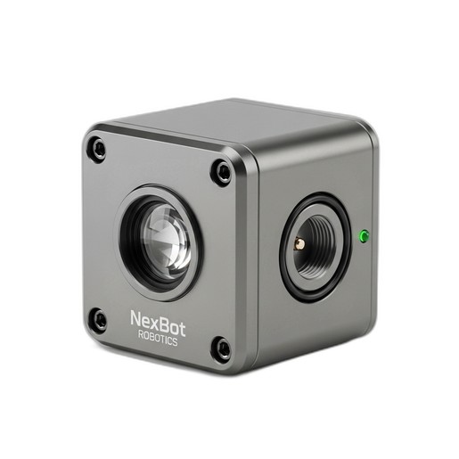
Integrating a force sensor might seem complex, but by following a structured approach, you can successfully equip your robot for force-sensitive tasks. This guide will walk you through the essential steps of integrating a single-axis force sensor, like the NexBot Drives SD312-006, into your robotic system.
Prerequisites: Gathering Your Tools and Components
Before you begin, ensure you have all the necessary hardware and software. A typical setup includes:
- Robot System: A 6-axis industrial robot arm and its controller.
- Force Sensor: A single-axis force sensor, such as the NexBot Drives SD312-006, rated for your application's expected forces.
- End-of-Arm Tooling (EOAT): The gripper, tool, or fixture that will interact with the workpiece.
- Mounting Hardware: A custom or off-the-shelf adapter plate to mount the sensor between the robot wrist and the EOAT.
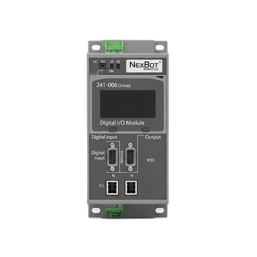
- I/O System: An IO-Link master and a compatible digital I/O module, like the NexBot Drives 241-006 Digital I/O Module, to connect the sensor's data stream to the robot controller's network (e.g., EtherCAT).
- Cabling: Appropriate M12 or similar industrial connectors and cables for power and communication.
- Software: The robot's programming environment and any necessary device description files (IODD for IO-Link) for the sensor.
- Safety: Ensure all work is performed with the robot in a de-energized and safe state, following your facility's lockout/tagout procedures.
Step 1: Mechanical Installation
The goal of mechanical installation is to create a rigid link where all forces exerted by the EOAT are transmitted through the sensor.
- Power Down: Completely power down the robot system and ensure it is mechanically and electrically locked out.
- Mount the Sensor: Securely fasten the force sensor to the robot's wrist flange using the correct size and grade of bolts. Ensure the mounting surfaces are clean and flat to prevent measurement inaccuracies.
- Attach the EOAT: Mount your end-of-arm tooling to the opposite face of the force sensor. The sensor is now sandwiched between the robot and the tool.
- Cable Management: Route the sensor cable along the robot arm, using the existing dress pack or cable management system. Leave enough slack to allow for the full range of motion of all robot axes without straining the cable or connectors.
Step 2: Electrical Wiring and Communication
With the sensor physically mounted, the next step is to connect it to the control system. The SD312-006 sensor uses a 24VDC supply and communicates via IO-Link, a powerful point-to-point protocol.
- Connect to IO-Link Master: Plug the sensor's M12 connector into an available port on your IO-Link master module. The IO-Link master will provide both the 24VDC power and handle the communication.
- Connect Master to Controller: The IO-Link master itself needs to be connected to your main industrial network. For systems using modules like the NexBot Drives 241-006, this is typically done via a fieldbus protocol like EtherCAT. Connect the I/O module to your robot controller's network switch or the previous device in the chain.
- Verify Connections: Double-check all connections for security. A loose connection is a common point of failure and can be difficult to troubleshoot later.
Step 3: Software Configuration
Now it's time to teach the robot controller how to understand the data coming from the sensor.
- Install Device Files: In your engineering software, install the IO-Link Device Description (IODD) file for your specific sensor model. This file tells the IO-Link master the sensor's identity, capabilities, and data structure.
- Configure the I/O Module: Configure the port on the IO-Link master to which the sensor is connected. The master will automatically detect the sensor and establish communication.
- Map the Data: Within the robot controller's I/O configuration, map the process data from the sensor to a variable or register within your robot's program. For a single-axis sensor, this is typically a single integer or real value representing the measured force in Newtons (or other units, depending on scaling).
Step 4: Calibration and Testing
Before programming complex logic, you must verify the sensor is reading correctly and establish a baseline.
- Zeroing (Taring): With the EOAT attached but not touching anything, command the sensor to perform a tare function. This sets the current reading (which accounts for the weight of the tool) as the new zero point. Most IO-Link sensors have a command for this.
- Manual Verification: In the robot's manual mode, gently press the EOAT against a fixed, sturdy surface. Monitor the force data variable in your programming environment. You should see the value increase as you apply pressure and decrease as you release it. This confirms the sensor is responding correctly.
- Directional Test: Verify that the force readings are positive or negative as expected based on the direction of force (e.g., pushing vs. pulling). If the sign is inverted, you may need to adjust a parameter in the sensor's configuration or simply multiply the value by -1 in your code.
Step 5: Programming Force-Guided Logic
With the sensor integrated and tested, you can now use its real-time feedback to control the robot's behavior. Common applications include:
- Search Routines: Program the robot to move along a path until the force sensor detects contact with a part, confirming its location.
- Constant Force Application: Create a feedback loop in your program where the robot continuously adjusts its position to maintain a constant force. This is essential for polishing, grinding, and deburring.
- Force-Limited Assembly: During insertion tasks, monitor the force to ensure a part is seating correctly. If the force exceeds a predefined threshold, it indicates a jam or misalignment, and the robot can be programmed to stop or take corrective action.
Conclusion: Ensuring a Successful Integration
Integrating a single-axis force sensor transforms your robot from a simple positioning device into a sophisticated tool capable of delicate and precise tasks. By following these steps—mechanical mounting, electrical wiring, software configuration, and testing—you can build a robust and reliable force-controlled system.
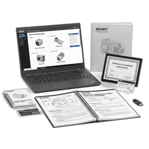
For complex applications or teams looking to accelerate their deployment timeline, professional assistance can be invaluable. Services like the NexBot Robotics 931-007 On-Site Commissioning Service provide access to certified technicians who can handle the entire integration process, from hardware setup and calibration to safety integration and cycle optimization, ensuring your system performs at its peak from day one.