Introduction: The Power of Flexibility
In today's competitive manufacturing landscape, agility is paramount. The ability to quickly adapt a production line to handle different products, processes, or batch sizes can be a significant advantage. For robotic automation, this agility is often unlocked by one key piece of technology: the Automatic Tool Changer (ATC). An ATC allows a single industrial robot to autonomously switch between various End-of-Arm Tools (EOATs), such as grippers, welders, sanders, or inspection sensors. This transforms a specialized robot into a multi-talented workhorse, maximizing its utilization and return on investment.
This guide provides a comprehensive, step-by-step walkthrough for integrating an ATC into your robotic cell. We will cover the critical phases from initial planning to final testing, ensuring a smooth and successful implementation.
Step 1: Pre-Integration Planning & Virtual Commissioning
Proper planning is the foundation of any successful robotics project. Before a single bolt is turned, a thorough plan will save you significant time, cost, and headaches down the line. Key considerations include robot payload, tool weight, cable management, and cell layout.
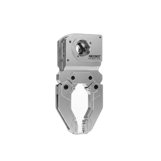
Payload Calculation: Ensure your robot's payload capacity can handle the combined weight of the ATC master plate, the heaviest tool plate, and the tool itself. The NexBot Robotics 421-001 Automatic Tool Changer, for example, supports a robust 25 kg payload, making it suitable for a wide range of demanding applications.
Cell Layout: Design the physical layout of the cell, including the robot's position, the tool stand or rack, and any fixtures. The tool stand must be positioned within the robot's reach envelope, allowing for a smooth, linear approach for tool changes.
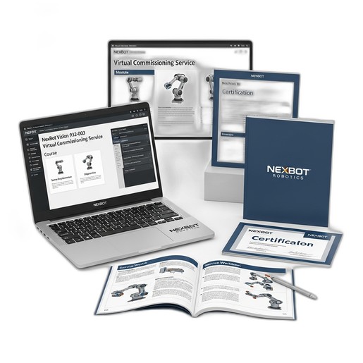
Virtual Commissioning: This is where modern integration truly shines. Leveraging a service like the NexBot Vision 932-003 Virtual Commissioning Service allows you to build a high-fidelity digital twin of your entire workcell. In this virtual environment, you can validate the cell layout, program and simulate tool change sequences, check for reachability issues, and perform collision detection—all before purchasing or installing physical hardware. This process de-risks the project and dramatically shortens the on-site commissioning time.
Step 2: Mechanical Installation
The physical installation involves mounting the two main components of the ATC system: the master plate on the robot and the tool plates on your EOATs.
- Mount the Master Plate: Securely fasten the ATC's master plate to the robot arm's wrist flange. Most industrial robots and ATCs adhere to a standard ISO 9409-1 bolt pattern, which simplifies this process. Use a torque wrench to tighten the bolts to the manufacturer's specifications to prevent vibration or loosening during operation.
- Mount the Tool Plates: Attach a separate tool plate to each of your EOATs. Whether it's a pneumatic gripper, a MIG welding torch, or a deburring tool, ensure the mounting is secure and repeatable.
- Install the Tool Stand: Mount the tool stand or rack in the location determined during the planning phase. The stand must hold the tools securely and present them to the robot at a precise, repeatable position and orientation for every tool change.
Step 3: Electrical and Pneumatic Connections
With the mechanical hardware in place, the next step is to connect the power, communication, and pneumatic lines.
Electrical Wiring: The NexBot Robotics 421-001 tool changer operates on standard 24VDC and utilizes the IO-Link communication protocol. IO-Link is a powerful point-to-point serial communication protocol that simplifies wiring and unlocks advanced diagnostic capabilities. Connect the IO-Link master (typically in the robot controller cabinet) to the ATC's master plate. This single cable can handle power, control signals (lock/unlock commands), and feedback signals (locked/unlocked status, tool present).
Pneumatic Hookup: The locking mechanism of most ATCs is pneumatically actuated. Connect clean, dry compressed air lines to the designated ports on the master plate for the lock and unlock functions. It is crucial to ensure the air supply meets the pressure and quality requirements specified by the ATC manufacturer to guarantee reliable operation of the fail-safe locking mechanism.
Step 4: Software Configuration and Programming
This phase brings the system to life within the robot's controller.
- I/O Configuration: Configure the robot controller's digital I/O to communicate with the ATC. If using IO-Link, this is often streamlined through the device's IODD (IO Device Description) file, which defines all parameters and process data.
- Define Tool Center Points (TCPs): Accuracy is everything in robotics. For each tool, you must precisely define its TCP—the functional point of the tool (e.g., the tip of a welding wire, the center of a gripper's jaws). An accurate TCP is essential for the robot to perform its task correctly.
- Program Tool Change Sequences: Create subroutines for the pick-up and drop-off sequences. A typical drop-off sequence involves the robot moving to a pre-defined approach point above the tool stand, moving down linearly to place the tool, issuing the 'unlock' command, verifying the unlock signal, and then retracting linearly. The pick-up sequence is the reverse of this process.
Step 5: Testing, Calibration, and Optimization
Before going into full production, rigorous testing is mandatory.
Dry Runs: Execute the tool change sequences and application programs at a very low speed. Carefully watch for any potential collisions, incorrect movements, or unexpected behavior.
Calibration: Verify the TCP of each tool after several tool changes to ensure the ATC provides high repeatability. Minor adjustments may be needed to the tool stand position or the programmed points to perfect the sequence.
Optimization: Once the system is proven to be safe and repeatable, you can gradually increase the robot's speed to optimize the cycle time. The goal is to make the tool change as fast as possible without sacrificing safety or reliability.
Application Example: A Multi-Process Fabrication Cell
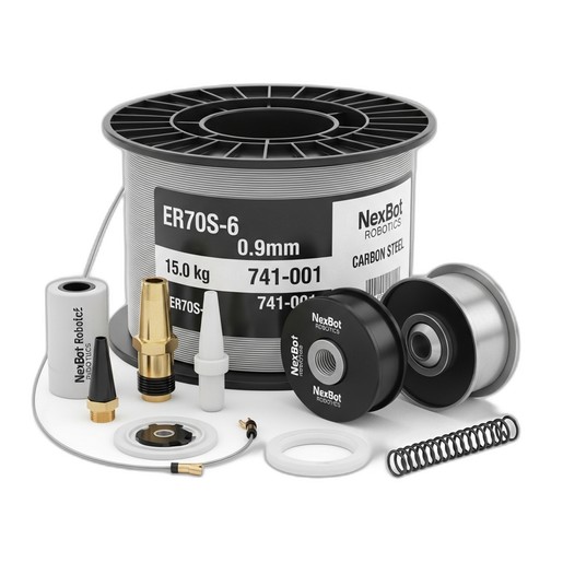
Imagine a cell designed to weld small sub-assemblies. The robot's first task is to use a gripper to pick up a metal plate and place it into a fixture. Using the ATC, the robot drops off the gripper at the tool stand and picks up a MIG welding torch. It then performs the required welds. For this critical welding step, consistency is key. Using a high-performance consumable like the NexBot Robotics 741-001 ER70S-6 MIG Welding Wire ensures a stable arc and minimal spatter, resulting in high-quality welds every time. After welding, the robot can even switch to a deburring tool to clean the edges before the cycle repeats. This entire multi-step process is achieved with a single robot, thanks to the flexibility afforded by the automatic tool changer.
By following these steps, you can successfully integrate an automatic tool changer, transforming your robotic cell into a versatile and highly efficient automation system.