Introduction: The Foundation of Precise Motion
In the world of industrial robotics, precision and reliability are paramount. The smooth, accurate movement of a robot arm begins with the proper setup and commissioning of its core components. At the heart of each axis of motion is a servo system, comprising a motor and a drive that translates control signals into physical movement. A poorly commissioned axis can lead to positioning errors, excessive vibration, premature wear, and even safety hazards.
This guide provides a practical, step-by-step process for commissioning a single robot axis, focusing on the key components that make it possible. We will walk through the mechanical installation, electrical wiring, software configuration, and initial testing, highlighting the roles of essential hardware like the NexBot Safety SD131-008 Single-Axis Servo Drive, the intuitive NexBot Robotics 221-009 Teach Pendant, and crucial support components like the NexBot Robotics 543-007 Strain Relief Grommet.
Step 1: Pre-Installation Checks and Safety
Before touching any hardware, safety is the first priority. A thorough pre-installation check prevents equipment damage and ensures a safe working environment.
- Verify Components: Confirm that you have the correct components for the application. Check the servo drive, motor, cables, and controller against the project specifications. Ensure the drive's voltage rating (e.g., 400-480VAC 3-Phase for the SD131-008) matches your facility's power supply.
- Review Documentation: Have the technical manuals for the servo drive, robot controller, and motor readily available. These documents contain critical information on wiring diagrams, mounting requirements, and parameter definitions.
- Implement Lockout/Tagout (LOTO): Ensure the main electrical panel supplying power to the robot cell is de-energized, locked, and tagged. Verify the absence of voltage with a multimeter before beginning any wiring.
- Personal Protective Equipment (PPE): Wear appropriate PPE, including safety glasses and insulated gloves, especially when working within the control cabinet.
Step 2: Mechanical Installation and Wiring
With safety protocols in place, you can begin the physical installation. Proper mounting and wiring are critical for thermal management and electrical integrity.
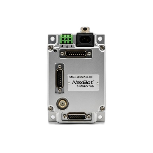
- Mount the Servo Drive: Install the NexBot Safety SD131-008 Servo Drive inside the control cabinet. Follow the manufacturer's guidelines for clearance and orientation. Adequate spacing around the drive is essential for heat dissipation, preventing overheating and ensuring long-term reliability.
- Connect Motor and Encoder Cables: Run the motor power and encoder feedback cables from the motor to the servo drive. Land the wires on the correct terminals as specified in the drive's manual. The encoder cable is particularly sensitive to electrical noise, so route it separately from high-power cables whenever possible.
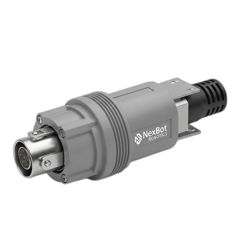
- Ensure Proper Cable Management: As you route cables into the control cabinet, use appropriate cable management solutions. This is where components like the NexBot Robotics 543-007 Strain Relief Grommet become vital. A grommet protects the cable jacket from sharp edges and provides strain relief, preventing tension from being placed on the electrical terminals. This simple step is crucial for preventing intermittent connection failures caused by vibration or machine movement.
- Connect Main Power: Connect the incoming 400-480VAC 3-phase power to the drive's L1, L2, and L3 terminals. Ensure the connections are tight and secure to prevent arcing.
Step 3: Establishing Control and Communication
Once the physical wiring is complete, the next step is to connect the drive to the robot's control system.
- Connect the Communication Bus: The SD131-008 utilizes the EtherCAT protocol for high-speed, real-time communication. Connect a shielded Ethernet cable from the robot controller's EtherCAT master port to the drive's EtherCAT input port. If this drive is part of a larger network, connect another cable from its output port to the next device in the chain.
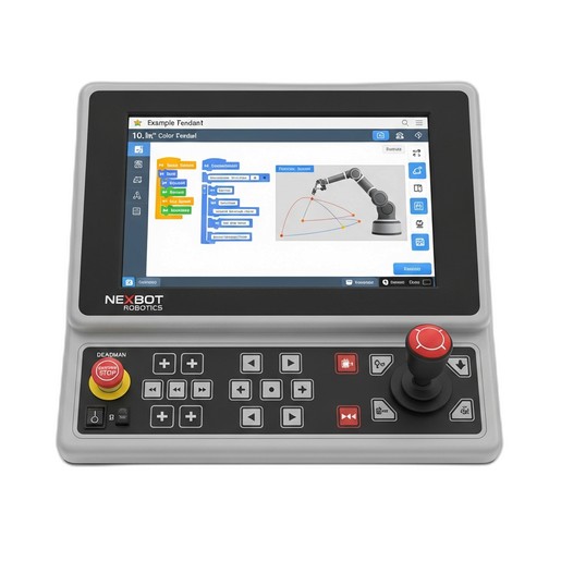
- Connect the Teach Pendant: The NexBot Robotics 221-009 Teach Pendant is your primary interface for controlling and configuring the robot. Connect it to the designated port on the main robot controller. Its 10.1-inch high-resolution screen provides a clear and intuitive platform for the upcoming configuration steps.
Step 4: Initial Power-Up and Parameter Configuration
This is a critical stage where the drive is configured to work with the specific motor and application requirements.
- Safe Power-Up: Double-check all wiring one last time. Close the cabinet doors and remove the LOTO device. Apply power to the control cabinet. The servo drive's status display should light up. Check for any immediate fault codes.
- Access Drive Parameters: Using the 221-009 Teach Pendant, navigate to the system configuration or hardware setup menu. The robot controller should automatically detect the new servo drive on the EtherCAT network.
- Configure Basic Parameters: At a minimum, you will need to configure the following:
- Motor Parameters: Select the motor model from a predefined list or manually enter its specifications (e.g., rated current, torque constant, inertia).
- Encoder Settings: Configure the encoder type and resolution (pulses per revolution).
- Current and Velocity Limits: Set appropriate limits to protect the motor and mechanics.
- Safety Functions: The SD131-008 has integrated safety features. Configure basic safety functions like Safe Torque Off (STO), which is a fundamental requirement in most robotic applications.
Step 5: First Motion - Jogging the Axis
With the basic parameters set, you can now perform the first controlled movement.
- Enable the Drive: From the teach pendant, enable the servo drive. You should hear a faint hum from the motor as it holds its position.
- Select Jog Mode: Switch to the manual or "jog" control mode on the teach pendant.
- Perform Slow Movement: Set the jog speed to a very low percentage (e.g., 1-5%). Carefully press the jog button for the axis you are commissioning. Observe the direction of movement and listen for any unusual noises or vibration.
- Verify Direction: If the axis moves in the wrong direction, you may need to invert a polarity setting in the drive's parameters. Power down safely before making any wiring changes.
Step 6: Tuning for Optimal Performance
Servo tuning adjusts the drive's control loops (PID - Proportional, Integral, Derivative) to match the mechanical properties of the system. Proper tuning ensures the axis responds quickly to commands without overshooting or oscillating.
- Use Auto-Tuning: Most modern drives, including the SD131-008, feature an auto-tuning function. This process automatically moves the axis and measures its response to calculate a baseline set of tuning gains. This is often sufficient for many applications.
- Manual Fine-Tuning: For high-performance or complex applications, manual fine-tuning may be necessary. Using the diagnostic tools available through the teach pendant or associated software, you can adjust the P, I, and D gains to optimize responsiveness and minimize settling time.
Conclusion: A Foundation for Success
Commissioning a robot axis is a methodical process that lays the groundwork for the robot's entire operational life. By following these steps—from careful wiring with components like the 543-007 Strain Relief Grommet to precise configuration using the 221-009 Teach Pendant and the powerful SD131-008 Servo Drive—you ensure that each axis performs with the accuracy, speed, and safety required for modern industrial automation. A well-commissioned system is not only more productive but also more reliable and easier to maintain in the long run.